MTI is a high-tech company specializing in PCB manufacturing, PCB assembly and parts procurement services with more than 20 years of experience. We are committed to producing various types of printed circuit boards, mainly including single-sided, double-sided, multi-layer circuit boards, high-precision HDI, flexible boards (FPC), rigid-flex boards (including HDI), metal circuit boards and their SMD plugin.Product line application areas include:industrial control.Fast response, strict quality control, best service, and strong technical support export our PCB products to global markets,including,Netherlands,Rwanda,Nauru,Guinea-Bissau,Qatar,Georgia

MTI möchte lange und stabile Geschäftsbeziehungen mit Kunden aus aller Welt aufbauen, die auf gegenseitigen Vorteilen und gegenseitigem Fortschritt beruhen. Wählen Sie MTI, um erfolgreich zu sein!

Name des Produkts 0,4mm Platine
Schlüsselwort 0.5 oz copper thickness pcb,0.6mm pcb
Ort der Herkunft China
Dicke der Platte 1~3,2mm
Anwendbare Industrien industrielle Steuerung, usw.
Dienst OEM/ODM-Fertigung
Zertifikat ISO-9001:2015, ISO-14001:2015,ISO-13485:2012.UL/CSA
Farbe der Lötmaske Schwarz
Vorteil Wir sorgen für gute Qualität und wettbewerbsfähige Preise, damit unsere Kunden davon profitieren.
Verkaufsland All over the world for example:Netherlands,Rwanda,Nauru,Guinea-Bissau,Qatar,Georgia


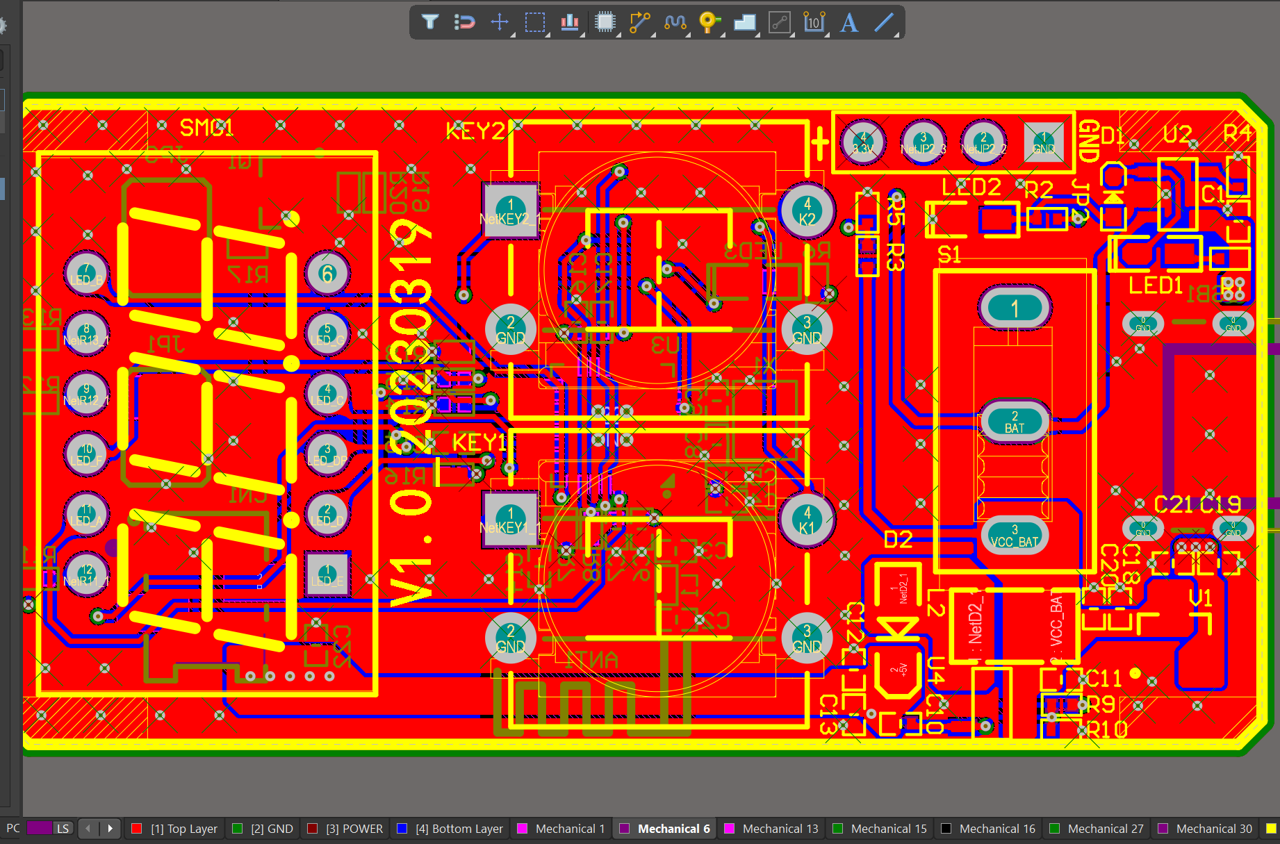
Wir haben reiche Erfahrung mit der Erstellung eines Layouts mit einer Softwareplattform wie Altium Designer. Dieses Layout zeigt Ihnen das genaue Aussehen und die Platzierung der Komponenten auf Ihrer Platine.

Einer unserer Hardware-Design-Services ist die Kleinserienfertigung, die es Ihnen ermöglicht, Ihre Idee schnell zu testen und die Funktionalität des Hardware-Designs und der Leiterplatte zu überprüfen.

Ihre Arbeitsergebnisse liegen immer vor dem Zeitplan und sind von höchster Qualität.


MTI ist ein professioneller Hersteller von Leiterplatten und PCBA und bietet Dienstleistungen aus einer Hand. Zu den wichtigsten Dienstleistungen des Unternehmens gehören PCB-Produktion, PCB-Montage und Einkauf von elektronischen Materialien, SMT-Patch, Schweißen von Leiterplatten, Leiterplatten-Steckverbindungen.

Unser Kundenkreis erstreckt sich über die wichtigsten Kontinente (Asien, Europa, Afrika, Amerika, Ozeanien) und umfasst verschiedene Branchen, darunter das Gesundheitswesen, die industrielle Steuerung

Name des Produkts 0,4 mm Platine
Schlüsselwort flex pcba,leiterplatte,0,8 mm leiterplatte
Ort der Herkunft China
Dicke der Platte 1~3,2mm
Anwendbare Industrien Sicherheit, usw.
Dienst OEM/ODM-Fertigung
Zertifikat ISO-9001:2015, ISO-14001:2015,ISO-13485:2012.UL/CSA
Farbe der Lötmaske Rot
Vorteil Wir sorgen für gute Qualität und wettbewerbsfähige Preise, damit unsere Kunden davon profitieren.
Verkaufsland In der ganzen Welt zum Beispiel: Sao Tome und Principe, Jamaika, Weihnachtsinsel, Gabun, Frankreich, Äquatorialguinea, Bulgarien

Wir haben reiche Erfahrung mit der Erstellung eines Layouts mit einer Softwareplattform wie Altium Designer. Dieses Layout zeigt Ihnen das genaue Aussehen und die Platzierung der Komponenten auf Ihrer Platine.

Ihre Arbeitsergebnisse liegen immer vor dem Zeitplan und sind von höchster Qualität.


Einer unserer Hardware-Design-Services ist die Kleinserienfertigung, die es Ihnen ermöglicht, Ihre Idee schnell zu testen und die Funktionalität des Hardware-Designs und der Leiterplatte zu überprüfen.


Seit über zwei Jahrzehnten widmet sich MTI der Bereitstellung umfassender OEM/ODM-Fertigungsdienstleistungen für Kunden in aller Welt. Dank unserer umfassenden Erfahrung in der Leiterplattenbestückung haben wir enge Kooperationsbeziehungen mit autorisierten Komponentenhändlern aufgebaut. So können wir alle benötigten Komponenten zu wettbewerbsfähigen Preisen beschaffen und unseren Kunden Kosteneffizienz garantieren.

Name des Produkts 0,2 mm Platine
Schlüsselwort pcb assembly manufacturer,PCBA Assembly,flexible pcb board,pcba manufacturing
Ort der Herkunft China
Dicke der Platte 2~3,2mm
Anwendbare Industrien Kommunikation, usw.
Dienst OEM/ODM-Fertigung
Zertifikat ISO-9001:2015, ISO-14001:2015,ISO-13485:2012.UL/CSA
Farbe der Lötmaske Schwarz
Vorteil Wir sorgen für gute Qualität und wettbewerbsfähige Preise, damit unsere Kunden davon profitieren.
Verkaufsland All over the world for example:Christmas Island,Kuwait,Mali,Tokelau,Timor-Leste,Malawi


Ihre Arbeitsergebnisse liegen immer vor dem Zeitplan und sind von höchster Qualität.

Einer unserer Hardware-Design-Services ist die Kleinserienfertigung, die es Ihnen ermöglicht, Ihre Idee schnell zu testen und die Funktionalität des Hardware-Designs und der Leiterplatte zu überprüfen.

Wir haben reiche Erfahrung mit der Erstellung eines Layouts mit einer Softwareplattform wie Altium Designer. Dieses Layout zeigt Ihnen das genaue Aussehen und die Platzierung der Komponenten auf Ihrer Platine.


MTI hat sich auf die schlüsselfertige Herstellung von Elektronikprodukten spezialisiert und bietet umfassende Lösungen von der Produktdokumentation bis zur Lieferung hochwertiger Produkte weltweit.

Mit einer breiten Palette, guter Qualität, angemessenen Preisen und stilvollem Design, sind unsere Produkte weit verbreitet in der Kommunikation verwendet.unsere Produkte sind weithin anerkannt und vertrauenswürdig durch die Nutzer und kann ständig wechselnden wirtschaftlichen und sozialen Anforderungen.wir begrüßen neue und alte Kunden aus allen Bereichen des Lebens, um uns für zukünftige Geschäftsbeziehungen und den gemeinsamen Erfolg zu kontaktieren!

Name des Produkts 0,1 mm Platine
Schlüsselwort 0.6mm pcb,circuit card assembly,pcb manufacturing,pcb assembly manufacturer,0.4mm pcb
Ort der Herkunft China
Dicke der Platte 2~3,2mm
Anwendbare Industrien industrielle Steuerung, usw.
Dienst OEM/ODM-Fertigung
Zertifikat ISO-9001:2015, ISO-14001:2015,ISO-13485:2012.UL/CSA
Farbe der Lötmaske Grün
Vorteil Wir sorgen für gute Qualität und wettbewerbsfähige Preise, damit unsere Kunden davon profitieren.
Verkaufsland All over the world for example:Germany,British Virgin Islands,Mongolia,India,Sweden


Ihre Arbeitsergebnisse liegen immer vor dem Zeitplan und sind von höchster Qualität.

Wir haben reiche Erfahrung mit der Erstellung eines Layouts mit einer Softwareplattform wie Altium Designer. Dieses Layout zeigt Ihnen das genaue Aussehen und die Platzierung der Komponenten auf Ihrer Platine.

Einer unserer Hardware-Design-Services ist die Kleinserienfertigung, die es Ihnen ermöglicht, Ihre Idee schnell zu testen und die Funktionalität des Hardware-Designs und der Leiterplatte zu überprüfen.


MTI hat sich auf die schlüsselfertige Herstellung von Elektronikprodukten spezialisiert und bietet umfassende Lösungen von der Produktdokumentation bis zur Lieferung hochwertiger Produkte weltweit.

Mit einer breiten Palette, gute Qualität, vernünftige Preise und stilvolle Designs, unsere Produkte sind weit verbreitet in der medizinischen verwendet.unsere Produkte sind weithin anerkannt und vertrauenswürdig durch die Nutzer und kann ständig wechselnden wirtschaftlichen und sozialen Anforderungen.wir begrüßen neue und alte Kunden aus allen Bereichen des Lebens, um uns für zukünftige Geschäftsbeziehungen und gemeinsamen Erfolg zu kontaktieren!

Name des Produkts PCB Montage Unternehmen
Schlüsselwort PCBA Assembly,pcb boards,pcb circuit board,eft pcb,flexible pcb board
Ort der Herkunft China
Dicke der Platte 2~3,2mm
Anwendbare Industrien medizinisch, usw.
Dienst OEM/ODM-Fertigung
Zertifikat ISO-9001:2015, ISO-14001:2015,ISO-13485:2012.UL/CSA
Farbe der Lötmaske Blau
Vorteil Wir sorgen für gute Qualität und wettbewerbsfähige Preise, damit unsere Kunden davon profitieren.
Verkaufsland All over the world for example:Isle of Man,Syria,Kuwait,Somalia,Dominica

Wir haben reiche Erfahrung mit der Erstellung eines Layouts mit einer Softwareplattform wie Altium Designer. Dieses Layout zeigt Ihnen das genaue Aussehen und die Platzierung der Komponenten auf Ihrer Platine.

Einer unserer Hardware-Design-Services ist die Kleinserienfertigung, die es Ihnen ermöglicht, Ihre Idee schnell zu testen und die Funktionalität des Hardware-Designs und der Leiterplatte zu überprüfen.

Ihre Arbeitsergebnisse liegen immer vor dem Zeitplan und sind von höchster Qualität.


Der Herstellungsprozess von gedruckten Schaltkreisen: Schritt-für-Schritt-Anleitung

Printed circuit boards (PCBs) are essential components in nearly all electronic devices today. These compact and efficient boards provide a platform for electrically connecting and powering various electronic components. The manufacturing process of PCBs involves several steps, from design and layout to printing and etching, to create a functional and reliable circuit board. In this article, we will discuss the step-by-step guide for the manufacturing process of printed circuit boards.

Step 1: Design and Layout
The first step in the manufacturing process of PCBs is the design and layout phase. This is where the schematic for the circuit board is created using computer-aided design (CAD) software. The layout of the PCB is also determined in this stage, including the placement of components and the routing of copper traces. The design is then converted into a Gerber file, which contains all the necessary information for the production process.

Step 2: Printing the Substrate
Once the design and layout are finalized, the next step is to print the substrate. The substrate is a thin insulating material, such as fiberglass or epoxy resin, on which the circuit will be mounted. This is done using a process called screen printing, where a layer of copper is deposited onto the substrate, creating a conductive pattern that corresponds to the circuit design. This copper layer is also known as the copper foil.

Step 3: Etching
The next step in the process is etching. This is where the excess copper is removed from the substrate, leaving only the desired copper trace pattern. The copper is etched away using a chemical reaction, typically using a solution of ferric chloride or ammonium persulfate. The Gerber file is used to create a stencil of the desired copper traces, which is then used as a mask during the etching process.

Step 4: Drilling
Once the copper has been etched away, the next step is drilling. Holes are drilled into the PCB at specific locations to accommodate components that will be mounted on the board. This is done using a precision drill press or a numerically-controlled (NC) drilling machine. The holes are then plated with copper to provide a conductive connection between the layers of the PCB.

Step 5: Plating
After drilling, the next step is plating. This is where a thin layer of conductive material, typically copper, is deposited onto the surface of the PCB. This process is essential for creating the necessary connections between the different layers of the board. The plating process can be done using various methods, including electroless plating, electroplating, and immersion plating.

Step 6: Solder Mask Application
Once the copper is plated, the next step is to apply a solder mask. The solder mask is a protective layer that covers the copper traces on the PCB, leaving only the areas where components will be soldered exposed. This helps to prevent short circuits and also provides insulation and protection to the board.

Step 7: Soldering
In this step, components such as resistors, capacitors, and integrated circuits are mounted onto the PCB using a process called soldering. The exposed copper traces and pads on the board are heated, and a small amount of solder is applied, creating a strong and reliable connection between the components and the board.

Step 8: Inspection and Testing
After the components are soldered, the finished board undergoes a series of inspection and testing procedures to ensure its functionality and quality. Automated optical inspection (AOI) is used to detect any defects or flaws in the board’s design or manufacturing. The board is also tested for continuity and functionality using specialized equipment.

Step 9: Surface Finishing
The final step in the manufacturing process is surface finishing. This is done to improve the durability, conductivity, and solderability of the PCB. The most common surface finishing techniques include electroless nickel immersion gold (ENIG), soldering, and hot air leveling (HASL). Each method offers different advantages, and the choice of surface finish depends on the application of the PCB.

The manufacturing process of printed circuit boards involves several complex and precise steps. From the initial design and layout to the final surface finish, each step is crucial in ensuring the functionality, reliability, and quality of the PCB. As technology continues to advance, the process of manufacturing PCBs is also evolving to meet the ever-increasing demands of the electronics industry.

Was sind die verschiedenen Arten von Leiterplatten und ihre Verwendungszwecke?

Gedruckte Schaltungen (PCB) sind wesentliche Komponenten in fast allen elektronischen Geräten. Sie sind das Rückgrat der modernen Technologie, denn sie ermöglichen die Verbindung und Organisation elektronischer Komponenten, so dass diese reibungslos funktionieren. Es gibt verschiedene Arten von Leiterplatten, jede mit ihrem eigenen Design und Zweck. In diesem Artikel werden wir die verschiedenen Arten von Leiterplatten und ihre Verwendungszwecke untersuchen.

Einseitige Leiterplatte:

Eine einseitige Leiterplatte ist die einfachste Art von Leiterplatten und wird am häufigsten verwendet. Wie der Name schon sagt, hat diese Art von Leiterplatte nur eine Schicht aus leitendem Material (normalerweise Kupfer) auf einer Seite. Passive Bauteile wie Widerstände, Kondensatoren und Dioden befinden sich auf der Oberseite der Leiterplatte, während sich alle Leiterbahnen und Lötpunkte auf der Unterseite befinden. Die Verwendung einseitiger Leiterplatten ist in der Regel auf einfache, kostengünstige Geräte wie Taschenrechner, Spielzeug und LED-Leuchten beschränkt.

Doppelseitige Leiterplatte:

Eine doppelseitige Leiterplatte hat leitendes Material auf beiden Seiten der Platte, was komplexere Schaltungsentwürfe ermöglicht. Diese Art von Leiterplatte wird häufig für fortschrittlichere elektronische Geräte wie Drucker, Mobiltelefone und Haushaltsgeräte verwendet. Die Bauteile sind auf beiden Seiten der Platine angebracht, und die Leiterbahnen werden durch Vias (kleine Bohrungen in der Platine) geführt, um die obere und die untere Schicht zu verbinden. Doppelseitige Leiterplatten sind relativ kostengünstig und vielseitiger als einseitige Leiterplatten.

Mehrschichtige PCB:

Wie der Name schon sagt, hat eine mehrlagige Leiterplatte mehrere Schichten aus leitendem und isolierendem Material, die zu einer einzigen Platte zusammengefügt sind. Diese Art von Leiterplatte wird in der Regel für fortschrittliche elektronische Geräte verwendet, bei denen der Platz begrenzt ist und eine hohe Funktionalität erforderlich ist. Mehrlagige Leiterplatten werden in der Regel in Computern, Routern und anderen komplexen Geräten verwendet. Sie können je nach Komplexität des Schaltungslayouts zwischen 4 und 20+ Lagen haben.

Starre Leiterplatte:

Eine starre Leiterplatte ist die gebräuchlichste Art von Leiterplatten und wird aus starren Materialien wie Glasfaser oder Epoxidharz hergestellt. Sie ist steif und kann nicht gebogen werden, wodurch sie sich für die meisten elektronischen Geräte eignet. Starre Leiterplatten gibt es in ein-, zwei- und mehrlagigen Konfigurationen.

Flexible Leiterplatte:

Eine flexible Leiterplatte, auch Flex PCB genannt, wird aus flexiblen Materialien wie Polyimid oder Polyester hergestellt. Diese Materialien ermöglichen es der Leiterplatte, sich zu biegen oder zu verdrehen, was sie ideal für elektronische Geräte macht, die eine individuelle Form benötigen. Flexible Leiterplatten werden häufig in der Unterhaltungselektronik eingesetzt, z. B. in Smartphones, Tablets und Wearables. Sie werden auch in der Luft- und Raumfahrt, im Militär und in der Medizin eingesetzt, wo Gewicht, Größe und Haltbarkeit entscheidende Faktoren sind.

Starr-Flex-Leiterplatte:

Eine starr-flexible Leiterplatte ist eine Kombination aus starrer und flexibler Leiterplatte und bietet beide Vorteile in einer einzigen Leiterplatte. Diese Art von Leiterplatte ist so konzipiert, dass sie einen starren Teil für Komponenten hat, die Stabilität erfordern, und einen flexiblen Teil für bewegliche oder biegsame Teile. Diese Leiterplatten werden häufig in Smartphones, Kameras und anderen elektronischen Geräten mit beweglichen Teilen verwendet.

Hochfrequenz-Leiterplatte:

Hochfrequenz-Leiterplatten sind für die Verarbeitung von Signalen im Hochfrequenzbereich, in der Regel über 1 GHz, ausgelegt. Sie werden aus speziellen Materialien wie PTFE (Polytetrafluorethylen) oder Keramik hergestellt, die einen geringen dielektrischen Verlust aufweisen und ein stabiles Signal aufrechterhalten können. Hochfrequenz-Leiterplatten werden in Anwendungen wie der Satellitenkommunikation, Radarsystemen und medizinischen Geräten eingesetzt.

PCB mit Metallkern:

Eine Metallkern-Leiterplatte hat eine Metallschicht als Basis, in der Regel Aluminium, mit einer Schicht aus isolierendem Material auf der Oberseite und einer Schicht aus Kupfer auf der Unterseite. Dieser Leiterplattentyp wird üblicherweise für Hochleistungsanwendungen verwendet, da die Metallschicht als Kühlkörper fungiert und die von den Komponenten erzeugte Wärme ableitet. Metallkern-Leiterplatten werden in der LED-Beleuchtung, in Netzteilen und in der Automobilelektronik eingesetzt.

High-Density Interconnect (HDI) PCB:

HDI-Leiterplatten sind so konzipiert, dass sie eine hohe Komponentendichte auf kompaktem Raum aufweisen. Sie verwenden Microvias, Blind Vias und Buried Vias zur Verbindung der Lagen und ermöglichen so ein komplexeres und kompakteres Schaltungsdesign. HDI-Leiterplatten werden in Smartphones, Tablets, Laptops und anderen kompakten elektronischen Geräten verwendet.

Integrierte Schaltung (IC) Substrate PCB:

IC-Substrat-Leiterplatten werden für die Montage der integrierten Schaltungen (ICs) elektronischer Geräte verwendet. Sie bestehen in der Regel aus Keramik oder Glas, und die ICs werden mit Hilfe der Drahtbond- oder Flip-Chip-Technologie darauf montiert. IC-Substrat-Leiterplatten werden in Computern, Telekommunikationsgeräten und anderen elektronischen Geräten verwendet, die moderne Mikrochips benötigen.

Zusammenfassend lässt sich sagen, dass es Leiterplatten in verschiedenen Formen, Größen und Konfigurationen gibt, die für unterschiedliche elektronische Geräte geeignet sind. Jede Art von Leiterplatte hat ihr eigenes Design und ihren eigenen Zweck, was sie zu wesentlichen Bestandteilen der modernen Technologie macht. So wie sich die Technologie weiterentwickelt, werden auch das Design und die Verwendung von Leiterplatten weiterentwickelt, was sie zu einem integralen Bestandteil unseres täglichen Lebens macht.

Einführung in gedruckte Schaltungen: Die Grundlagen verstehen

Printed Circuit Boards (PCB) are widely used in today’s electronic devices, such as smartphones, computers, and even household appliances. They are an essential component in the manufacturing of electronic products and have greatly evolved over the years. In this article, we will delve into the basics of PCB – how they work, their types, and their key components.

What is a Printed Circuit Board?

A Printed Circuit Board, also known as a PCB, is a thin board made of non-conductive material, usually fiberglass, that serves as the base for mounting and connecting electronic components. It is designed to provide a stable platform for the attachment of electrical components and serves as an interconnected pathway for the flow of electric signals between them. The board is printed with thin layers of conductive material, typically copper, which forms the circuitry and allows for the transmission of electricity.

Types of Printed Circuit Boards

There are various types of PCB  each serving a different purpose. The most commonly used types are single-sided, double-sided, and multi-layer PCBs.

1. Single-Sided PCB: These are the most basic and commonly used type of PCB. They have a layer of conductive material, usually copper, on one side of the board, and the components are mounted on the other side. Single-sided PCB are mainly used in simple electronics with relatively few components.

2. Double-Sided PCB: As the name suggests, double-sided PCB have a layer of conductive material on both sides of the board. This allows for greater flexibility in design and enables the use of more complex circuits.

3. Multi-Layer PCB: These PCBs consist of several layers of conductive material separated by insulating layers, with the components mounted on the outer layers. Multi-layer PCB are used in complex electronics where space is limited and compact designs are required.

Key Components of a Printed Circuit Board

1. Substrate: The substrate is the base material of the PCB, usually made of fiberglass or composite epoxy material. It provides the necessary support for the conductive layers and components.

2. Conductive Layers: These are thin layers of conductive material, typically copper, that make up the circuitry of the PCB. They are usually etched onto the substrate and are responsible for carrying the electrical signals between components.

3. Components: Electronic components such as resistors, capacitors, and integrated circuits (ICs) are mounted on the PCB. They are connected to the conductive layers through holes called vias or by traces on the surface of the board.

4. Solder Mask: The solder mask is a protective layer that covers the conductive layers, leaving only the connection points exposed. It protects the PCB from corrosion and protects against short circuits.

5. Silkscreen: This is the layer on top of the solder mask that is used to label and identify components and their placement on the board. It usually contains information such as component names, reference numbers, and polarity.

How do Printed Circuit Boards Work?

The functioning of a PCB is relatively simple. The components on the board are connected by a network of conductive paths, also known as traces, which allow the flow of electricity between them. These paths are created by etching the conductive layers, usually copper, to form a pattern that connects the components in the desired configuration.

The components are mounted on the board by soldering them to the conductive pads, which serve as connection points. The soldering process involves heating the pads and components, then melting the soldering material, usually a mixture of tin and lead, to create a strong and permanent bond.

Advantages of Using Printed Circuit Boards

The use of PCBs offers several advantages over other methods of connecting electronic components. These include:

1. Compact and Lightweight: PCBs are compact and lightweight, making them ideal for use in smaller electronic devices.

2. High Reliability: Due to their design and manufacturing process, PCBs have proven to be highly reliable and durable.

3. Cost-effective: The use of PCBs significantly reduces the cost of production and assembly of electronic devices, making them a cost-effective option.

4. Easy to Repair and Replace: In the event of a faulty component, the PCB can be easily repaired or replaced without the need for complex and time-consuming re-wiring.

Schlussfolgerung

Printed Circuit Boards are vital components in today’s electronic devices, allowing for compact and efficient designs. They come in various types, each serving different purposes, and are made up of key components such as the substrate, conductive layers, components, solder mask, and silkscreen. Their use offers numerous advantages, making them an essential element in the manufacturing of electronic products. As technology continues to advance, we can expect to see further advancements in the design and use of PCBs.


The Evolution of Printed Circuit Boards: From Early Designs to Modern Technology

Printed circuit boards (PCBs) are an essential component in most modern electronic devices. They serve as the foundation for electronic connections and are responsible for routing the electrical signals between the different components of a circuit. PCBs have undergone significant changes since their first inception, and their evolution has closely mirrored advancements in technology.

The Early Days

The origin of PCBs can be traced back to the late 19th century when they were used in a rudimentary form for telephone exchanges. These early PCBs were known as “printed wires” and were created by attaching thin metal wires to a wooden board. This early form of PCB was used to connect telephone switchboards and reduce the need for manual rewiring.

In the early 1900s, scientists started experimenting with the use of thin copper foils on flat bases to create electrical circuits. This led to the invention of “printed” wires on flat boards made by hand, which also reduced the size and complexity of electronic devices. These early PCBs were primarily used in military equipment and radios during World War II.

The Advent of Mass Production

The first commercially successful mass-produced PCB was developed in 1942 by Paul Eisler, an Austrian inventor. His innovative design used conductive ink on a Bakelite board, marking the beginning of modern PCB technology. His creation was initially used in the radio industry, but its use quickly spread to other electronic devices.

The introduction of transistors in the 1950s revolutionized the electronic industry. This development led to smaller and more efficient devices, and PCBs played a crucial role in their production. The early PCB designs used point-to-point connections, which limited the complexity and size of circuits. However, with the introduction of transistors, manufacturers were able to add more components to a PCB, leading to the creation of more advanced electronic devices.

The Rise of Integrated Circuits

In the late 1950s, scientists developed the first integrated circuit (IC), which was a significant breakthrough in the evolution of PCBs. ICs allowed for the miniaturization of electronic components, making devices smaller, faster, and more efficient. This technology paved the way for PCBs to become an integral part of electronic devices, from televisions and radios to computers and mobile phones.

As electronic devices became more complex and the demand for smaller and more efficient devices increased, PCBs continued to evolve. In the 1960s, the through-hole method of assembling components on a PCB was introduced, which allowed for the use of larger and more complex circuits. This method involved drilling holes into the board and inserting component wires through them before soldering them in place.

The Rise of Surface Mount Technology (SMT)

In the 1980s, surface mount technology (SMT) was introduced, bringing another significant change to the manufacturing of PCBs. SMT involves attaching components directly onto the surface of a PCB, eliminating the need for drilling holes. This method increased the complexity and density of electronic circuits, making devices even smaller and more powerful.

SMT also allowed for the use of automated assembly processes, reducing the cost and time required to produce PCBs. This resulted in the mass production of electronic devices, making them more accessible and affordable for the general population.

The Evolution Continues

The evolution of PCBs is ongoing, with new advancements and innovations being introduced regularly. Today, manufacturers are using advanced techniques, such as multi-layer PCBs and flexible PCBs, to further improve the performance and capabilities of electronic devices.

Multi-layer PCBs have multiple layers of circuitry, allowing for more complex circuits without increasing the size of the board. This technology is used in devices such as computers and smartphones, where space is limited, but functionality is crucial.

Flexible PCBs, as the name suggests, can be bent or twisted without damaging the circuitry. This technology has allowed for the creation of devices such as foldable smartphones and wearable technology, where rigid PCBs would not be suitable.

In addition to these advancements, there has also been a push towards more environmentally friendly PCB production. Lead-free and halogen-free materials are being used, and recycling methods are being developed to reduce the impact of electronic waste on the environment.