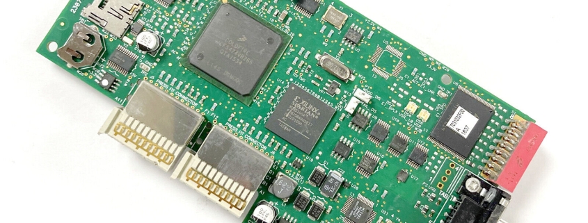
1070 pcb
MTI is a manufacturer of high-precision printed circuit board (PCB).We specialize in the manufacture of high precision double-sided and multilayer printed circuit boards, We provide high quality products and faster service for high-tech companies.
We have a group of experienced staff and high-quality management team, set up a complete quality assurance system. Products include FR-4 PCB, Metal PCB and RFPCB (ceramic PCB, PTFE PCB), etc. Have rich experience in the production of thick copper PCB, RF PCB, high Tg PCB, HDI PCB.With ISO9001, ISO14001, TS16949, ISO 13485, RoHS certifications.
| Product name | 1070 pcb |
| Keyword | circuit card assembly process,pcb manufacturing and assembly,12v led pcb |
| Place of Origin | China |
| Board Thickness | 2~3.2mm |
| Applicable Industries | medical equipment, etc. |
| Service | OEM/ODM manufacturing |
| Certificate | ISO-9001:2015, ISO-14001:2015,ISO-13485:2012.UL/CSA |
| Solder Mask Color | Red |
| Advantage | We keep good quality and competitive price to ensure our customers benefit |
| Sales country | All over the world for example:Niger,Dominican Republic,Wake Island,Paraguay,Romania,Tanzania |
One of our Hardware Design Services is small-batch manufacturing, which allows you to test your idea quickly and verify the functionality of the hardware design and PCB board.

Your deliverables are always ahead of schedule and of the highest quality.
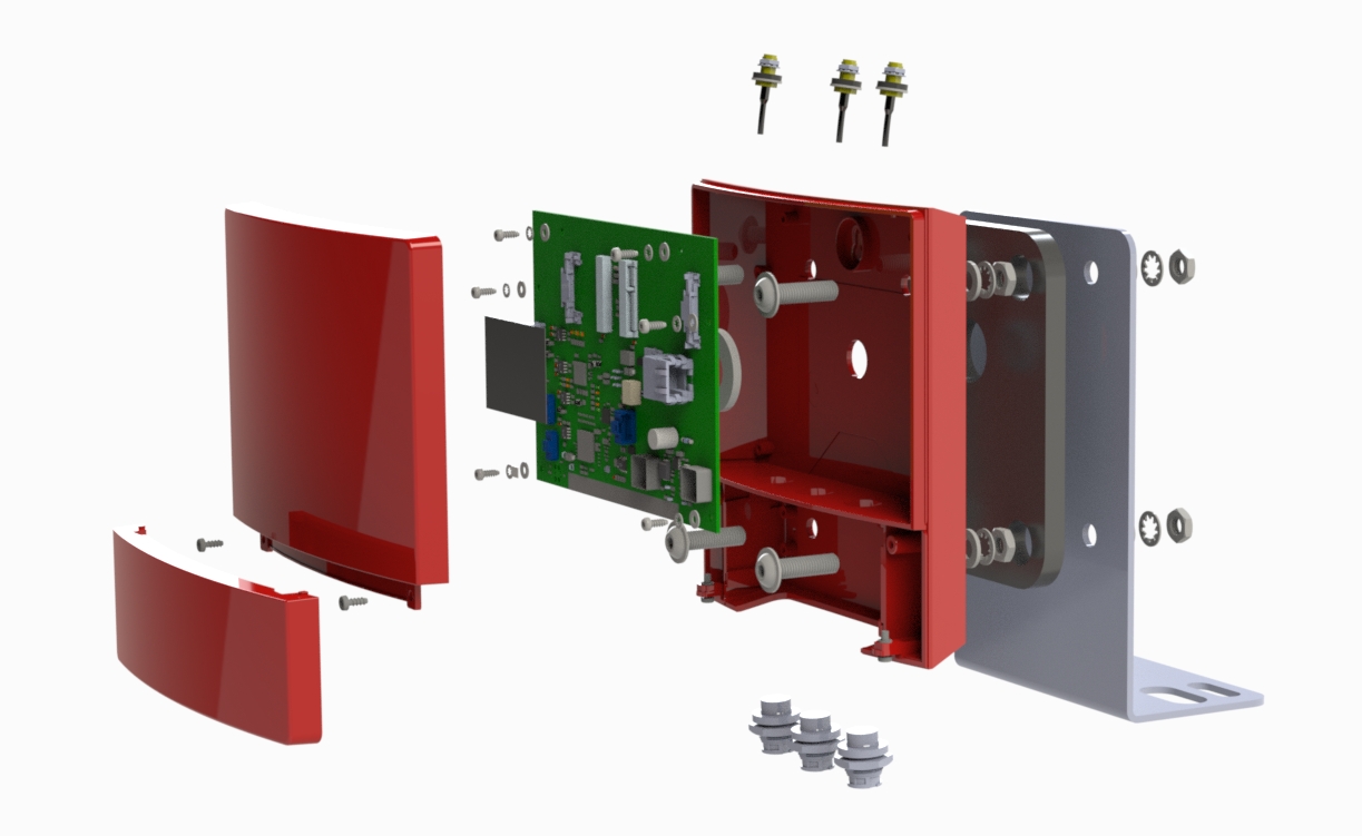
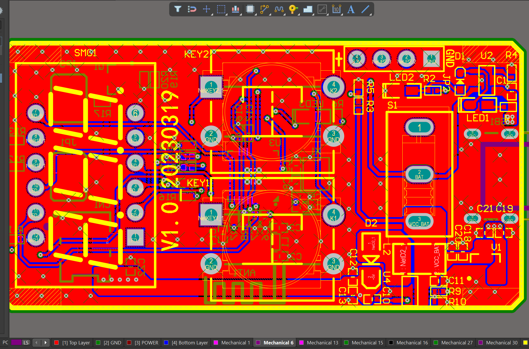
We have rich experience engineer to create a layout using a software platform like Altium Designer. This layout shows you the exact appearance and placement of the components on your board.
FAQs Guide
2.What is the minimum distance required between components on a PCB?
3.How does the type of PCB connection (wired or wireless) impact its design and features?
4.Can PCBs be made with different thicknesses?
5.What are the differences between a prototype and production PCB?
6.How does the hole size and shape impact the manufacturing process of a PCB?
7.What is impedance control and why is it important in PCBs?
8.How does the type of PCB finish affect its durability and lifespan?
1.How do surface mount components differ from through-hole components in a PCB?
We pay attention to user experience and product quality, and provide the best product quality and lowest production cost for cooperative customers.
Surface mount components (SMD) and through-hole components (THD) are two different types of electronic components used in printed circuit boards (PCBs). The main difference between them lies in their method of mounting onto the PCB.
1. Mounting Method:
The main difference between SMD and THD components is their mounting method. SMD components are mounted directly onto the surface of the PCB, while THD components are inserted into holes drilled into the PCB and soldered on the other side.
2. Size:
SMD components are generally smaller in size compared to THD components. This is because SMD components do not require leads or pins for mounting, allowing for a more compact design. THD components, on the other hand, have leads or pins that need to be inserted into the PCB, making them larger in size.
3. Space Efficiency:
Due to their smaller size, SMD components allow for a more space-efficient design on the PCB. This is especially important in modern electronic devices where space is limited. THD components take up more space on the PCB due to their larger size and the need for holes to be drilled.
4. Cost:
SMD components are generally more expensive than THD components. This is because SMD components require more advanced manufacturing techniques and equipment, making them costlier to produce.
5. Assembly Process:
The assembly process for SMD components is automated, using pick-and-place machines to accurately place the components onto the PCB. This makes the process faster and more efficient compared to THD components, which require manual insertion and soldering.
6. Electrical Performance:
SMD components have better electrical performance compared to THD components. This is because SMD components have shorter leads, resulting in less parasitic capacitance and inductance, leading to better signal integrity.
In summary, SMD components offer a more compact design, better electrical performance, and a faster assembly process, but at a higher cost. THD components, on the other hand, are larger in size, less expensive, and can handle higher power and voltage ratings. The choice between SMD and THD components depends on the specific requirements of the PCB design and the intended use of the electronic device.
2.What is the minimum distance required between components on a PCB?
We have advanced production equipment and technology to meet the needs of customers, and can provide customers with high quality, low priced 1070 pcb products.
The minimum distance required between components on a PCB depends on various factors such as the type of components, their size, and the manufacturing process used. Generally, the minimum distance between components is determined by the manufacturer’s design rules and guidelines.
For surface mount components, the minimum distance between components is typically 0.2mm to 0.3mm. This distance is necessary to ensure that the solder paste does not bridge between the pads during the reflow process.
For through-hole components, the minimum distance between components is typically 1mm to 2mm. This distance is necessary to ensure that the components do not interfere with each other during the assembly process.
In high-speed and high-frequency applications, the minimum distance between components may need to be increased to avoid signal interference and crosstalk. In these cases, the manufacturer’s design rules and guidelines should be followed closely.
Overall, the minimum distance between components on a PCB should be determined based on the specific requirements of the design and the capabilities of the manufacturing process.
3.How does the type of PCB connection (wired or wireless) impact its design and features?
Our products & services cover a wide range of areas and meet the needs of different fields.
The type of PCB connection, whether wired or wireless, can have a significant impact on the design and features of the PCB. Some of the key ways in which the type of connection can impact the PCB design and features are:
1. Size and form factor: Wired PCBs typically require physical connectors and cables, which can add to the overall size and form factor of the PCB. On the other hand, wireless PCBs do not require physical connectors and cables, allowing for a smaller and more compact design.
2. Power consumption: Wired PCBs require a constant supply of power to function, whereas wireless PCBs can operate on battery power. This can impact the power consumption and battery life of the device, which in turn can affect the overall design and features of the PCB.
3. Flexibility and mobility: Wireless PCBs offer greater flexibility and mobility as they do not have physical connections that restrict movement. This can be advantageous in applications where the device needs to be moved or used in different locations.
4. Data transfer speed: Wired PCBs typically have faster data transfer speeds compared to wireless PCBs. This can impact the design and features of the PCB, as certain applications may require high-speed data transfer.
5. Cost: The type of connection can also impact the cost of the PCB. Wired PCBs may require additional components such as connectors and cables, which can add to the overall cost. Wireless PCBs, on the other hand, may require more advanced technology and components, making them more expensive.
6. Reliability: Wired PCBs are generally considered more reliable as they have a physical connection, which is less prone to interference or signal loss. Wireless PCBs, on the other hand, may be more susceptible to interference and signal loss, which can impact their reliability.
Overall, the type of PCB connection can significantly impact the design and features of the PCB, and it is important to carefully consider the specific requirements of the application when choosing between wired and wireless connections.
4.Can PCBs be made with different thicknesses?
We operate our 1070 pcb business with integrity and honesty.
Yes, PCBs (printed circuit boards) can be made with different thicknesses. The thickness of a PCB is determined by the thickness of the copper layer and the thickness of the substrate material. The copper layer thickness can range from 0.5 oz to 3 oz, while the substrate material thickness can range from 0.2 mm to 3.2 mm. The most common thicknesses for PCBs are 1.6 mm and 0.8 mm, but custom thicknesses can be requested from PCB manufacturers. The thickness of a PCB can affect its mechanical strength, thermal properties, and electrical performance.
5.What are the differences between a prototype and production PCB?
We have a good reputation and image in the industry. The quality and price advantage of 1070 pcb products is an important factor in our hard overseas market.
1. Purpose: The main difference between a prototype and production PCB is their purpose. A prototype PCB is used for testing and validation of a design, while a production PCB is used for mass production and commercial use.
2. Design: Prototype PCBs are usually hand-soldered and have a simpler design compared to production PCBs. Production PCBs are designed with more precision and complexity to meet the specific requirements of the final product.
3. Materials: Prototype PCBs are often made with cheaper materials such as FR-4, while production PCBs use higher quality materials such as ceramic or metal core for better performance and durability.
4. Quantity: Prototype PCBs are usually made in small quantities, while production PCBs are manufactured in large quantities to meet the demand of the market.
5. Cost: Due to the use of cheaper materials and smaller quantities, prototype PCBs are less expensive compared to production PCBs. Production PCBs require a larger investment due to the use of higher quality materials and larger quantities.
6. Lead time: Prototype PCBs have a shorter lead time as they are made in smaller quantities and can be hand-soldered. Production PCBs have a longer lead time as they require more complex manufacturing processes and larger quantities.
7. Testing: Prototype PCBs are extensively tested to ensure the design is functional and meets the required specifications. Production PCBs also undergo testing, but the focus is more on quality control and consistency in mass production.
8. Documentation: Prototype PCBs may not have detailed documentation as they are often hand-soldered and used for testing purposes. Production PCBs have detailed documentation to ensure consistency in manufacturing and for future reference.
9. Modifications: Prototype PCBs are easier to modify and make changes to, as they are not mass-produced. Production PCBs are more difficult to modify as any changes can affect the entire production process.
10. Reliability: Production PCBs are designed and manufactured to be more reliable and durable, as they will be used in the final product. Prototype PCBs may not have the same level of reliability as they are used for testing and may not undergo the same level of quality control.
6.How does the hole size and shape impact the manufacturing process of a PCB?
We continue to invest in research and development and continue to launch innovative products.
The hole size and shape on a PCB can impact the manufacturing process in several ways:
1. Drilling process: The size and shape of the holes determine the type of drill bit and the drilling speed required for creating the holes. Smaller holes require smaller drill bits and slower drilling speeds, while larger holes require larger drill bits and faster drilling speeds. The shape of the hole can also affect the stability of the drill bit and the accuracy of the drilling process.
2. Plating process: After the holes are drilled, they need to be plated with a conductive material to create electrical connections between different layers of the PCB. The size and shape of the holes can affect the plating process, as larger or irregularly shaped holes may require more plating material and longer plating times.
3. Soldering process: The size and shape of the holes can also impact the soldering process. Smaller holes may require more precise placement of components and more careful soldering techniques, while larger holes may allow for easier soldering.
4. Component placement: The size and shape of the holes can also affect the placement of components on the PCB. Smaller holes may limit the size of components that can be used, while larger holes may allow for more flexibility in component placement.
5. PCB design: The size and shape of the holes can also impact the overall design of the PCB. Different hole sizes and shapes may require different routing and layout strategies, which can affect the overall functionality and performance of the PCB.
Overall, the size and shape of the holes on a PCB can significantly impact the manufacturing process and should be carefully considered during the design phase to ensure efficient and accurate production.
7.What is impedance control and why is it important in PCBs?
We enjoy high authority and influence in the industry and continue to innovate products and service models.
Impedance control is the ability to maintain a consistent electrical impedance throughout a printed circuit board (PCB). It is important in PCBs because it ensures that signals can travel through the board without distortion or loss of quality.
Impedance control is particularly important in high-speed digital and analog circuits, where even small variations in impedance can cause signal reflections and distortions. This can lead to errors in data transmission and affect the overall performance of the circuit.
In addition, impedance control is crucial in ensuring signal integrity and reducing electromagnetic interference (EMI). By maintaining a consistent impedance, the PCB can effectively filter out unwanted signals and prevent them from interfering with the desired signals.
Overall, impedance control is essential for achieving reliable and high-quality performance in PCBs, especially in complex and sensitive electronic systems. It requires careful design and manufacturing techniques, such as controlled trace widths and spacing, to achieve the desired impedance levels.
8.How does the type of PCB finish affect its durability and lifespan?
I have a comprehensive after -sales service system, which can pay attention to market trends in time and adjust our strategy in a timely manner.
The type of PCB finish can have a significant impact on the durability and lifespan of a PCB. The finish is the final coating applied to the surface of the PCB to protect it from environmental factors and ensure proper functionality. Some common types of PCB finishes include HASL (Hot Air Solder Leveling), ENIG (Electroless Nickel Immersion Gold), and OSP (Organic Solderability Preservative).
1. HASL (Hot Air Solder Leveling):
HASL is a popular and cost-effective finish that involves coating the PCB with a layer of molten solder and then leveling it with hot air. This finish provides good solderability and is suitable for most applications. However, it is not very durable and can be prone to oxidation, which can affect the performance of the PCB over time. HASL finish also has a limited shelf life and may require rework after a certain period.
2. ENIG (Electroless Nickel Immersion Gold):
ENIG is a more advanced and durable finish compared to HASL. It involves depositing a layer of nickel and then a layer of gold on the surface of the PCB. This finish provides excellent corrosion resistance and is suitable for high-reliability applications. ENIG finish also has a longer shelf life and does not require rework as frequently as HASL.
3. OSP (Organic Solderability Preservative):
OSP is a thin organic coating applied to the surface of the PCB to protect it from oxidation. It is a cost-effective finish and provides good solderability. However, OSP finish is not as durable as ENIG and may require rework after a certain period. It is also not suitable for high-temperature applications.
In summary, the type of PCB finish can affect its durability and lifespan in the following ways:
– Corrosion resistance: Finishes like ENIG and OSP provide better corrosion resistance compared to HASL, which can affect the performance and lifespan of the PCB.
– Shelf life: Finishes like ENIG have a longer shelf life compared to HASL, which may require rework after a certain period.
– Solderability: All finishes provide good solderability, but ENIG and OSP are more suitable for high-reliability applications.
– Environmental factors: The type of finish can also affect the PCB’s resistance to environmental factors like humidity, temperature, and chemicals, which can impact its durability and lifespan.
In conclusion, choosing the right type of PCB finish is crucial for ensuring the durability and longevity of the PCB. Factors such as the application, environmental conditions, and budget should be considered when selecting the appropriate finish for a PCB.
Tags:pcb manufacture and assembly
