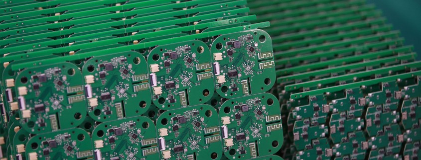
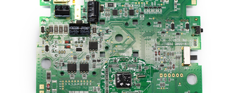
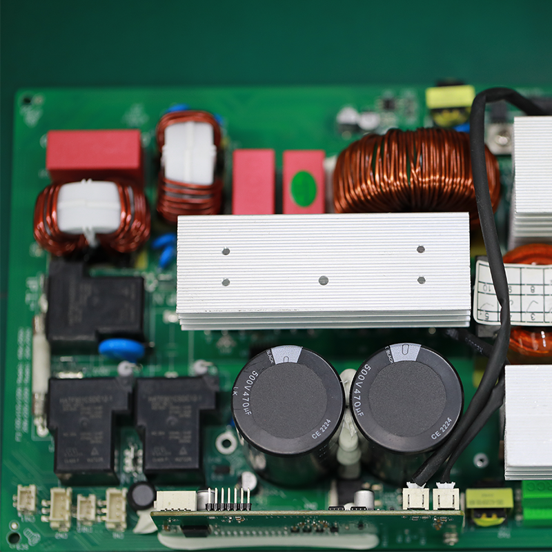
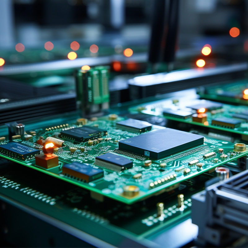
MTI is a professional manufacturer of PCB and PCBA , we supply one-stop service. The company’s main services include PCB production, PCB Assembly and electronic materials purchasing, SMT patch, circuit board welding, circuit board plug-in.
Our clientele spans across major continents (Africa,Asia,Oceania)and encompasses various industries, including healthcare,military
| Product name | 1000 watt amplifier pcb |
| Keyword | pcb assembly and production process,2.4ghz pcb antenna,automated circuit board assembly,1 4 jack pcb |
| Place of Origin | China |
| Board Thickness | 1~3.2mm |
| Applicable Industries | military, etc. |
| Service | OEM/ODM manufacturing |
| Certificate | ISO-9001:2015, ISO-14001:2015,ISO-13485:2012.UL/CSA |
| Solder Mask Color | Black |
| Advantage | We keep good quality and competitive price to ensure our customers benefit |
| Sales country | All over the world for example:Colombia,French Polynesia,Morocco,Lithuania,United Arab Emirates,Micronesia, Federated States of,Sweden,North Korea,Saint Pierre and Miquelon |
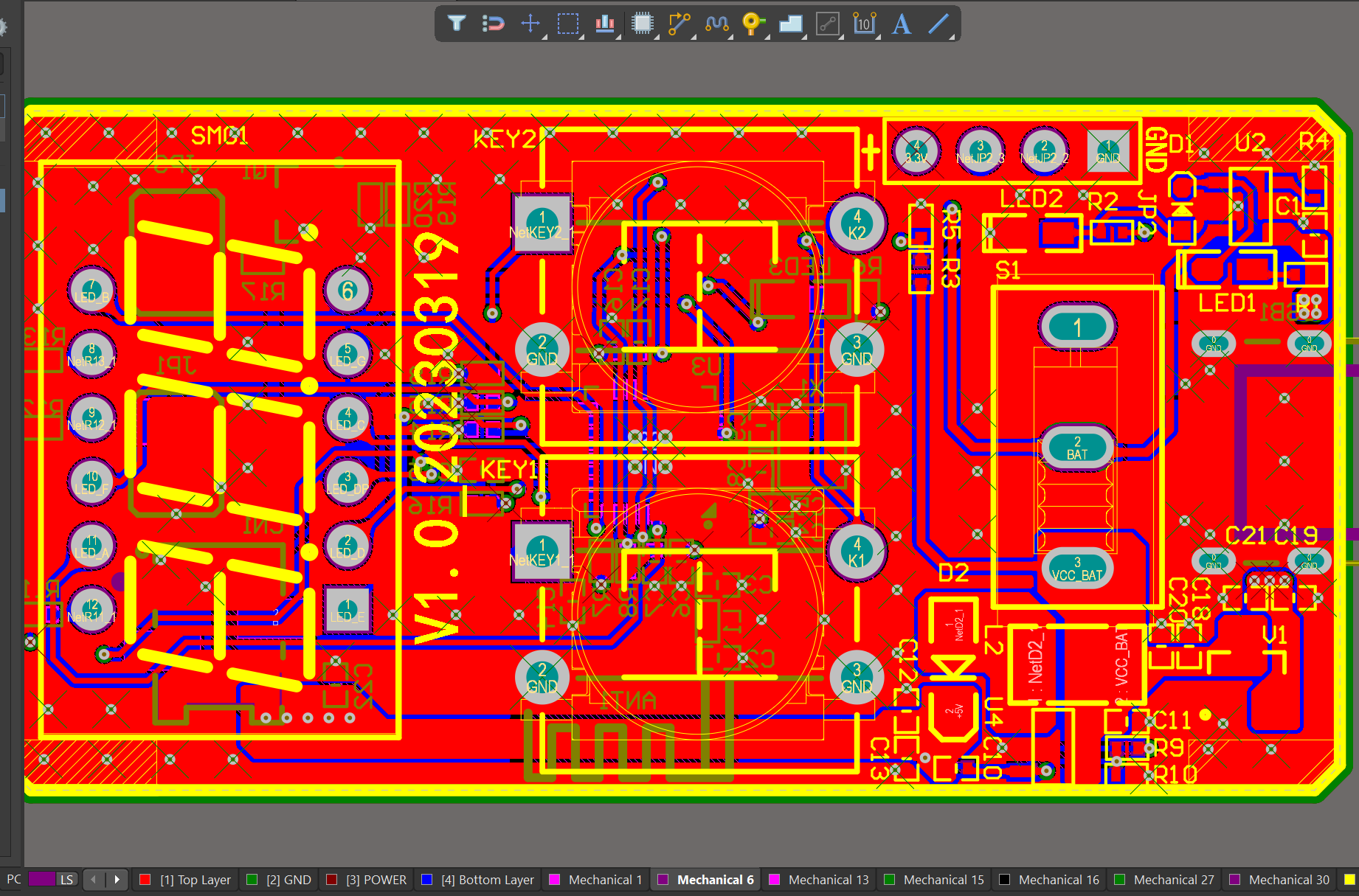
We have rich experience engineer to create a layout using a software platform like Altium Designer. This layout shows you the exact appearance and placement of the components on your board.
Your deliverables are always ahead of schedule and of the highest quality.
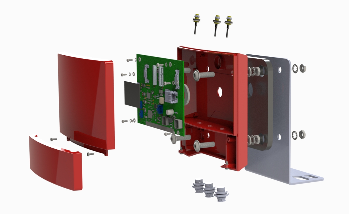
One of our Hardware Design Services is small-batch manufacturing, which allows you to test your idea quickly and verify the functionality of the hardware design and PCB board.

FAQs Guide
2.What is impedance control and why is it important in PCBs?
3.What makes a PCB resistant to environmental factors such as moisture and temperature?
4.What are the factors to consider when choosing the right PCB material for a specific application?
5.Can PCBs be designed with high-speed and high-frequency applications in mind?
1.What are the different types of through-hole mounting techniques used in PCBs?
We have flexible production capacity. Whether you are large orders or small orders, you can produce and release goods in a timely manner to meet customer needs.
1. Through-Hole Plating: This is the most common through-hole mounting technique, where the holes in the PCB are plated with a conductive material, usually copper, to create a connection between the layers of the board.
2. Through-Hole Soldering: In this technique, the components are inserted into the plated holes and then soldered to the pads on the opposite side of the board. This provides a strong mechanical connection and good electrical conductivity.
3. Through-Hole Riveting: In this method, the components are inserted into the plated holes and then secured with a rivet or pin. This is commonly used for high-power components or in applications where the board may experience high levels of vibration.
4. Through-Hole Press-Fit: This technique involves inserting the component leads into the plated holes and then pressing them into place using a specialized tool. This provides a strong mechanical connection without the need for soldering.
5. Through-Hole Wave Soldering: In this method, the components are inserted into the plated holes and then passed over a wave of molten solder, which creates a strong solder joint between the component leads and the PCB pads.
6. Through-Hole Reflow Soldering: This technique is similar to wave soldering, but instead of passing over a wave of molten solder, the board is heated in a controlled environment to melt the solder and create a strong joint.
7. Through-Hole Hand Soldering: This is a manual method of soldering where the components are inserted into the plated holes and then soldered by hand using a soldering iron. This is commonly used for small-scale production or for repairs.
8. Through-Hole Pin-in-Paste: This technique involves inserting the component leads into the plated holes and then applying solder paste to the holes before reflow soldering. This provides a strong mechanical connection and good solder joints.
9. Through-Hole Pin-in-Hole: In this method, the component leads are inserted into the plated holes and then bent to form a right angle, creating a secure mechanical connection. This is commonly used for components with large leads, such as electrolytic capacitors.
10. Through-Hole Hand Assembly: This is a manual method of assembly where the components are inserted into the plated holes and then secured with hand tools, such as screws or nuts. This is commonly used for large or heavy components that require additional support.
2.What is impedance control and why is it important in PCBs?
We enjoy high authority and influence in the industry and continue to innovate products and service models.
Impedance control is the ability to maintain a consistent electrical impedance throughout a printed circuit board (PCB). It is important in PCBs because it ensures that signals can travel through the board without distortion or loss of quality.
Impedance control is particularly important in high-speed digital and analog circuits, where even small variations in impedance can cause signal reflections and distortions. This can lead to errors in data transmission and affect the overall performance of the circuit.
In addition, impedance control is crucial in ensuring signal integrity and reducing electromagnetic interference (EMI). By maintaining a consistent impedance, the PCB can effectively filter out unwanted signals and prevent them from interfering with the desired signals.
Overall, impedance control is essential for achieving reliable and high-quality performance in PCBs, especially in complex and sensitive electronic systems. It requires careful design and manufacturing techniques, such as controlled trace widths and spacing, to achieve the desired impedance levels.
3.What makes a PCB resistant to environmental factors such as moisture and temperature?
We should perform well in market competition, and the prices of 1000 watt amplifier pcb products have a great competitive advantage.
1. Material Selection: The choice of materials used in the PCB can greatly affect its resistance to environmental factors. Materials such as FR-4, polyimide, and ceramic are known for their high resistance to moisture and temperature.
2. Conformal Coating: Applying a conformal coating to the PCB can provide an additional layer of protection against moisture and temperature. This coating acts as a barrier between the PCB and the environment, preventing any moisture or contaminants from reaching the components.
3. Solder Mask: The solder mask used on the PCB can also play a role in its resistance to environmental factors. A high-quality solder mask can provide a protective layer against moisture and temperature, preventing any damage to the components.
4. Component Placement: Proper placement of components on the PCB can also contribute to its resistance to environmental factors. Components that are sensitive to moisture or temperature should be placed away from areas that are prone to these factors, such as near heat sources or in areas with high humidity.
5. Thermal Management: Adequate thermal management is crucial for maintaining the temperature of the PCB within safe limits. This can be achieved through the use of heat sinks, thermal vias, and proper ventilation.
6. Design Considerations: The design of the PCB can also impact its resistance to environmental factors. Factors such as trace width, spacing, and routing can affect the PCB’s ability to withstand temperature changes and moisture exposure.
7. Testing and Quality Control: Proper testing and quality control measures can ensure that the PCB is built to withstand environmental factors. This includes testing for moisture resistance, thermal cycling, and other environmental stressors.
8. Compliance with Standards: Following industry standards and regulations for PCB design and manufacturing can also contribute to its resistance to environmental factors. These standards often include guidelines for material selection, component placement, and testing procedures.
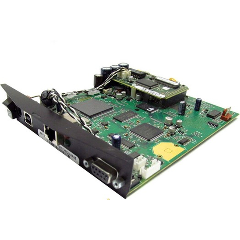
4.What are the factors to consider when choosing the right PCB material for a specific application?
We are centered on customers and always pay attention to customers’ needs for 1000 watt amplifier pcb products.
1. Electrical properties: The electrical properties of the PCB material, such as dielectric constant, loss tangent, and insulation resistance, should be carefully considered to ensure optimal performance for the specific application.
2. Thermal properties: The thermal conductivity and coefficient of thermal expansion of the PCB material are important factors to consider, especially for applications that require high power or operate in extreme temperatures.
3. Mechanical properties: The mechanical strength, stiffness, and flexibility of the PCB material should be evaluated to ensure it can withstand the physical stresses and strains of the application.
4. Chemical resistance: The PCB material should be resistant to any chemicals or solvents that it may come into contact with during its use.
5. Cost: The cost of the PCB material should be considered, as it can vary significantly depending on the type and quality of the material.
6. Availability: Some PCB materials may be more readily available than others, which can affect production timelines and costs.
7. Manufacturing process: The chosen PCB material should be compatible with the manufacturing process, such as etching, drilling, and plating, to ensure efficient and reliable production.
8. Environmental factors: The application environment, such as humidity, moisture, and exposure to UV light, should be taken into account when selecting a PCB material to ensure it can withstand these conditions.
9. Signal integrity: For high-frequency applications, the PCB material should have low signal loss and good signal integrity to prevent interference and ensure accurate signal transmission.
10. RoHS compliance: If the application requires compliance with environmental regulations, such as the Restriction of Hazardous Substances (RoHS) directive, the PCB material should be chosen accordingly.
5.Can PCBs be designed with high-speed and high-frequency applications in mind?
We attach importance to the innovation ability and team spirit of employees, have advanced R & D facilities and laboratories, and have a good quality management system.
Yes, PCBs can be designed with high-speed and high-frequency applications in mind. This involves careful consideration of the layout, trace routing, and component placement to minimize signal loss and interference. Specialized materials and techniques, such as controlled impedance routing and differential pairs, can also be used to improve signal integrity and reduce noise. Additionally, the use of advanced simulation and analysis tools can help optimize the design for high-speed and high-frequency performance.
Tags:12 layer pcb thickness , 3080 fe pcb , 1 oz pcb thickness
