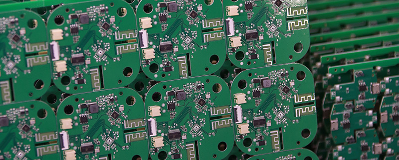
108 key pcb
MTI is a professional manufacturer of PCB and PCBA , we supply one-stop service. The company’s main services include PCB production, PCB Assembly and electronic materials purchasing, SMT patch, circuit board welding, circuit board plug-in.
Our clientele spans across major continents (America,Africa,Europe)and encompasses various industries, including healthcare,testing instruments
| Product name | 108 key pcb |
| Keyword | 3080 founders pcb,fast turn printed circuit board assembly,prototype circuit board assembly,pcb manufacturer,printed circuit assembly |
| Place of Origin | China |
| Board Thickness | 2~3.2mm |
| Applicable Industries | security, etc. |
| Service | OEM/ODM manufacturing |
| Certificate | ISO-9001:2015, ISO-14001:2015,ISO-13485:2012.UL/CSA |
| Solder Mask Color | Yellow |
| Advantage | We keep good quality and competitive price to ensure our customers benefit |
| Sales country | All over the world for example:Italy,Estonia,El Salvador,Peru,Guinea-Bissau,Eritrea |
One of our Hardware Design Services is small-batch manufacturing, which allows you to test your idea quickly and verify the functionality of the hardware design and PCB board.

Your deliverables are always ahead of schedule and of the highest quality.
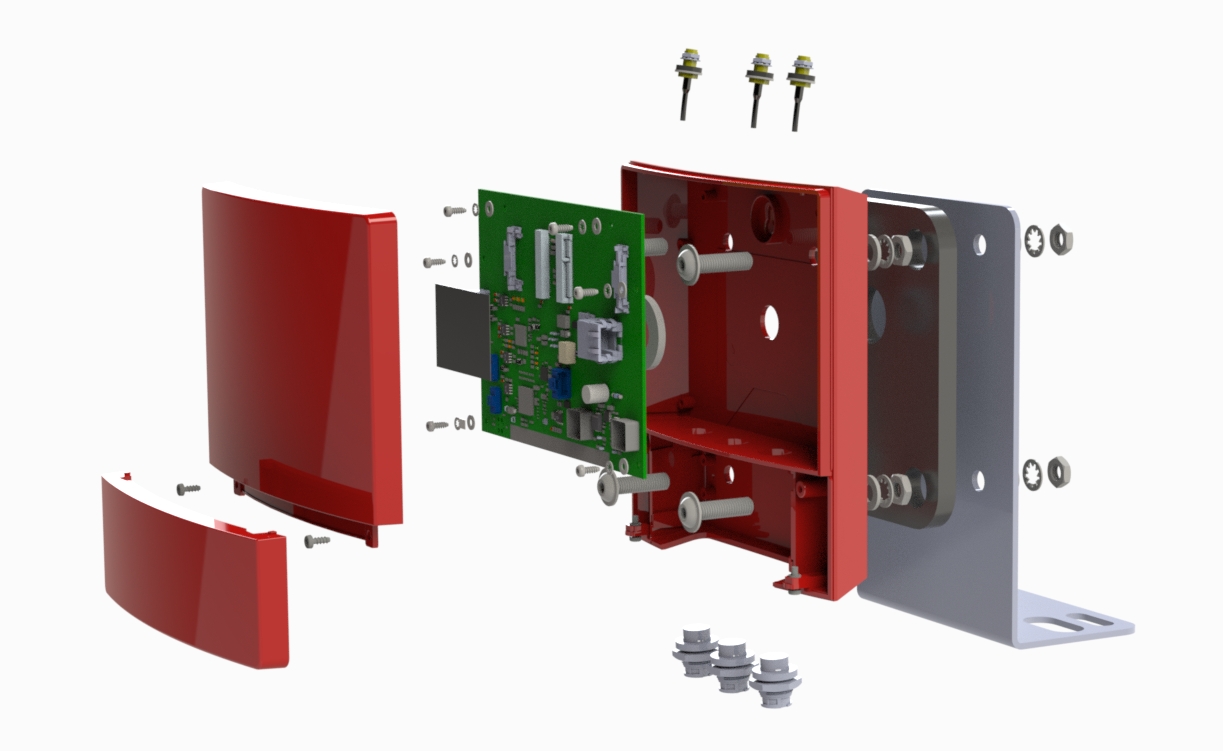
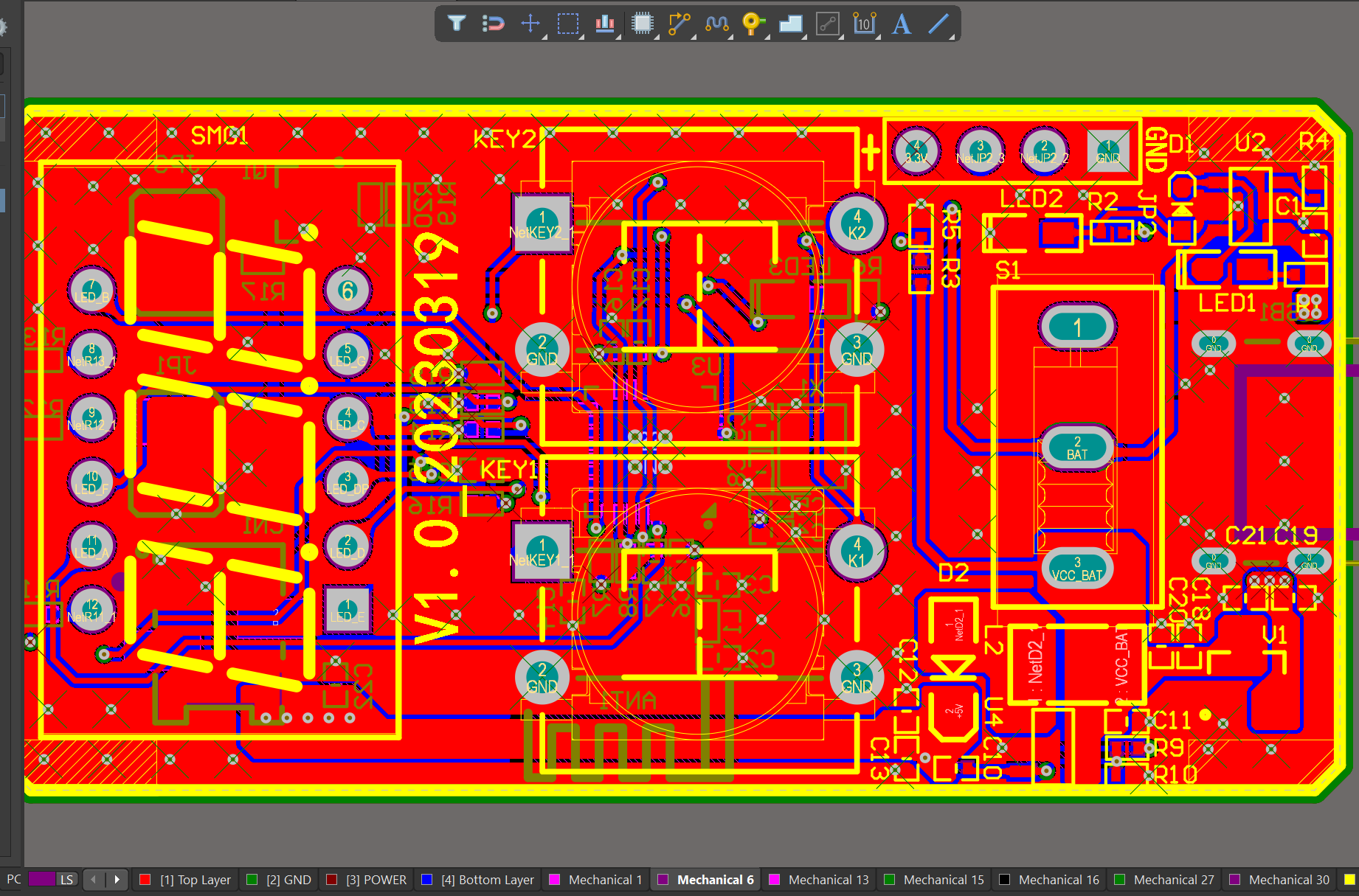
We have rich experience engineer to create a layout using a software platform like Altium Designer. This layout shows you the exact appearance and placement of the components on your board.
FAQs Guide
2.How does the hole size and shape impact the manufacturing process of a PCB?
3.What is the difference between single-sided and double-sided PCBs?
4.How important is the trace width and spacing in a PCB design?
5.How does the type of laminate material used impact the PCB design?
6.What are the key features of a PCB?
1.What are the factors to consider when choosing the right PCB material for a specific application?
We are centered on customers and always pay attention to customers’ needs for 108 key pcb products.
1. Electrical properties: The electrical properties of the PCB material, such as dielectric constant, loss tangent, and insulation resistance, should be carefully considered to ensure optimal performance for the specific application.
2. Thermal properties: The thermal conductivity and coefficient of thermal expansion of the PCB material are important factors to consider, especially for applications that require high power or operate in extreme temperatures.
3. Mechanical properties: The mechanical strength, stiffness, and flexibility of the PCB material should be evaluated to ensure it can withstand the physical stresses and strains of the application.
4. Chemical resistance: The PCB material should be resistant to any chemicals or solvents that it may come into contact with during its use.
5. Cost: The cost of the PCB material should be considered, as it can vary significantly depending on the type and quality of the material.
6. Availability: Some PCB materials may be more readily available than others, which can affect production timelines and costs.
7. Manufacturing process: The chosen PCB material should be compatible with the manufacturing process, such as etching, drilling, and plating, to ensure efficient and reliable production.
8. Environmental factors: The application environment, such as humidity, moisture, and exposure to UV light, should be taken into account when selecting a PCB material to ensure it can withstand these conditions.
9. Signal integrity: For high-frequency applications, the PCB material should have low signal loss and good signal integrity to prevent interference and ensure accurate signal transmission.
10. RoHS compliance: If the application requires compliance with environmental regulations, such as the Restriction of Hazardous Substances (RoHS) directive, the PCB material should be chosen accordingly.
2.How does the hole size and shape impact the manufacturing process of a PCB?
We continue to invest in research and development and continue to launch innovative products.
The hole size and shape on a PCB can impact the manufacturing process in several ways:
1. Drilling process: The size and shape of the holes determine the type of drill bit and the drilling speed required for creating the holes. Smaller holes require smaller drill bits and slower drilling speeds, while larger holes require larger drill bits and faster drilling speeds. The shape of the hole can also affect the stability of the drill bit and the accuracy of the drilling process.
2. Plating process: After the holes are drilled, they need to be plated with a conductive material to create electrical connections between different layers of the PCB. The size and shape of the holes can affect the plating process, as larger or irregularly shaped holes may require more plating material and longer plating times.
3. Soldering process: The size and shape of the holes can also impact the soldering process. Smaller holes may require more precise placement of components and more careful soldering techniques, while larger holes may allow for easier soldering.
4. Component placement: The size and shape of the holes can also affect the placement of components on the PCB. Smaller holes may limit the size of components that can be used, while larger holes may allow for more flexibility in component placement.
5. PCB design: The size and shape of the holes can also impact the overall design of the PCB. Different hole sizes and shapes may require different routing and layout strategies, which can affect the overall functionality and performance of the PCB.
Overall, the size and shape of the holes on a PCB can significantly impact the manufacturing process and should be carefully considered during the design phase to ensure efficient and accurate production.
3.What is the difference between single-sided and double-sided PCBs?
Our mission is to provide customers with the best solutions for 108 key pcb.
Single-sided PCBs have copper traces and components on only one side of the board, while double-sided PCBs have copper traces and components on both sides of the board. This allows for more complex circuit designs and a higher density of components on a double-sided PCB. Single-sided PCBs are typically used for simpler circuits and are less expensive to manufacture, while double-sided PCBs are used for more complex circuits and are more expensive to manufacture.
4.How important is the trace width and spacing in a PCB design?
Our 108 key pcb products have competitive and differentiated advantages, and actively promote digital transformation and innovation.
The trace width and spacing in a PCB design are crucial factors that can greatly affect the performance and reliability of the circuit. Here are some reasons why:
1. Current carrying capacity: The trace width determines the amount of current that can flow through the trace without causing excessive heating. If the trace width is too narrow, it can lead to overheating and damage to the circuit.
2. Voltage drop: The trace width also affects the voltage drop across the trace. A narrow trace will have a higher resistance, resulting in a higher voltage drop. This can cause a decrease in the voltage level at the end of the trace, affecting the performance of the circuit.
3. Signal integrity: The spacing between traces is critical for maintaining signal integrity. If the spacing is too narrow, it can lead to crosstalk and interference between signals, resulting in errors and malfunctions in the circuit.
4. Thermal management: The spacing between traces also plays a role in thermal management. Adequate spacing between traces allows for better air circulation, which helps dissipate heat from the circuit. This is especially important for high-power circuits.
5. Manufacturing constraints: The trace width and spacing also need to be considered in the manufacturing process. If the traces are too close together, it can be challenging to etch and inspect the PCB, leading to manufacturing defects.
In summary, the trace width and spacing are critical parameters that need to be carefully considered in PCB design to ensure proper functioning and reliability of the circuit.
5.How does the type of laminate material used impact the PCB design?
As one of the top 108 key pcb manufacturers in China, we take this very seriously.
The type of laminate material used can impact the PCB design in several ways:
1. Electrical properties: Different laminate materials have different electrical properties, such as dielectric constant, loss tangent, and insulation resistance. These properties can affect the signal integrity and impedance of the PCB, which can impact the performance of the circuit.
2. Thermal properties: Some laminate materials have better thermal conductivity than others, which can affect the heat dissipation of the PCB. This is especially important for high-power applications where heat management is crucial.
3. Mechanical properties: The mechanical properties of the laminate material, such as stiffness and flexibility, can impact the overall durability and reliability of the PCB. This is important for applications where the PCB may be subjected to physical stress or vibration.
4. Cost: Different laminate materials have different costs, which can impact the overall cost of the PCB. Some materials may be more expensive but offer better performance, while others may be more cost-effective but have lower performance.
5. Manufacturing process: The type of laminate material used can also impact the manufacturing process of the PCB. Some materials may require specialized equipment or processes, which can affect the production time and cost.
6. Compatibility with components: Certain laminate materials may not be compatible with certain components, such as high-frequency components or components that require specific soldering temperatures. This can limit the design options and affect the functionality of the PCB.
Overall, the type of laminate material used can significantly impact the design, performance, and cost of a PCB. It is important to carefully consider the requirements of the circuit and choose a suitable laminate material to ensure optimal performance and reliability.
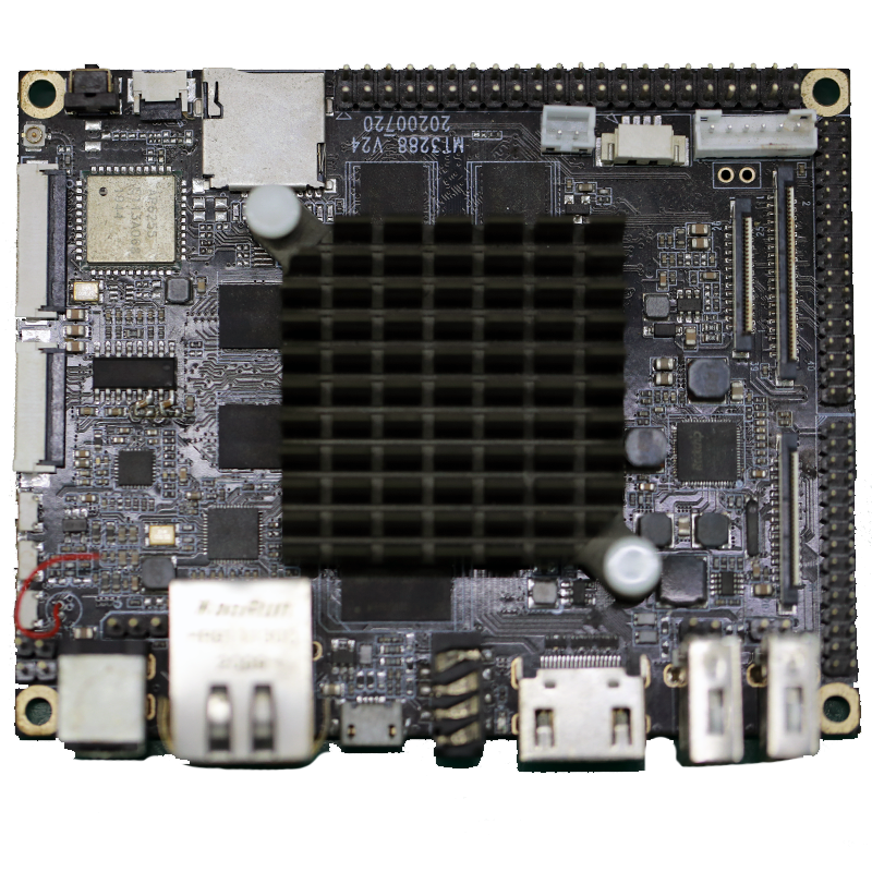
6.What are the key features of a PCB?
We are committed to providing personalized solutions and established long -term strategic cooperative relationships with customers.
1. Substrate: The base material on which the circuit is printed, usually made of fiberglass or composite epoxy.
2. Conductive Traces: Thin copper lines that connect the components on the PCB.
3. Pads: Small copper areas on the PCB surface where components are soldered.
4. Vias: Holes drilled through the PCB to connect the different layers of the circuit.
5. Solder Mask: A layer of protective material that covers the copper traces and pads, preventing accidental short circuits.
6. Silkscreen: A layer of ink that is printed on the PCB to label the components and provide other useful information.
7. Components: Electronic devices such as resistors, capacitors, and integrated circuits that are mounted on the PCB.
8. Mounting Holes: Holes drilled on the PCB to allow it to be securely attached to a larger device or enclosure.
9. Copper Pour: Large areas of copper that are used to provide a common ground or power plane for the circuit.
10. Edge Connectors: Metal contacts on the edge of the PCB that allow it to be connected to other circuits or devices.
11. Solder Bridges: Small areas of exposed copper that allow for the connection of two or more traces.
12. Test Points: Small pads or holes on the PCB that allow for testing and troubleshooting of the circuit.
13. Silkscreen Legend: Printed text or symbols on the silkscreen layer that provide additional information about the PCB and its components.
14. Designators: Letters or numbers printed on the silkscreen layer to identify specific components on the PCB.
15. Reference Designators: A combination of letters and numbers that identify the location of a component on the PCB according to the schematic diagram.
Tags:2.4 ghz pcb antenna design , printed circuit board assembly suppliers
