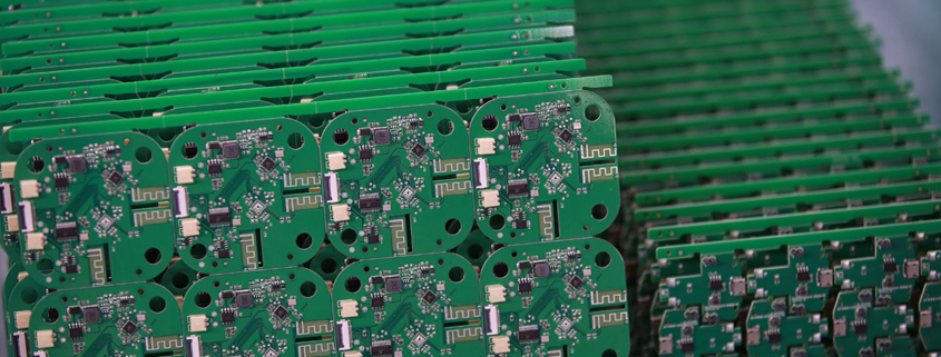
12v battery charger pcb board
MTI is a professional manufacturer of PCB and PCBA , we supply one-stop service. The company’s main services include PCB production, PCB Assembly and electronic materials purchasing, SMT patch, circuit board welding, circuit board plug-in.
Our clientele spans across major continents (Africa,Oceania,Asia)and encompasses various industries, including healthcare,consumer electronics
| Product name | 12v battery charger pcb board |
| Keyword | 3080 fe pcb,100 watt amplifier pcb,120mm pcb |
| Place of Origin | China |
| Board Thickness | 2~3.2mm |
| Applicable Industries | security, etc. |
| Service | OEM/ODM manufacturing |
| Certificate | ISO-9001:2015, ISO-14001:2015,ISO-13485:2012.UL/CSA |
| Solder Mask Color | Black |
| Advantage | We keep good quality and competitive price to ensure our customers benefit |
| Sales country | All over the world for example:French Polynesia,Russia,Christmas Island,Colombia,Paracel Islands,Tajikistan,Clipperton Island,Malta,Cambodia |
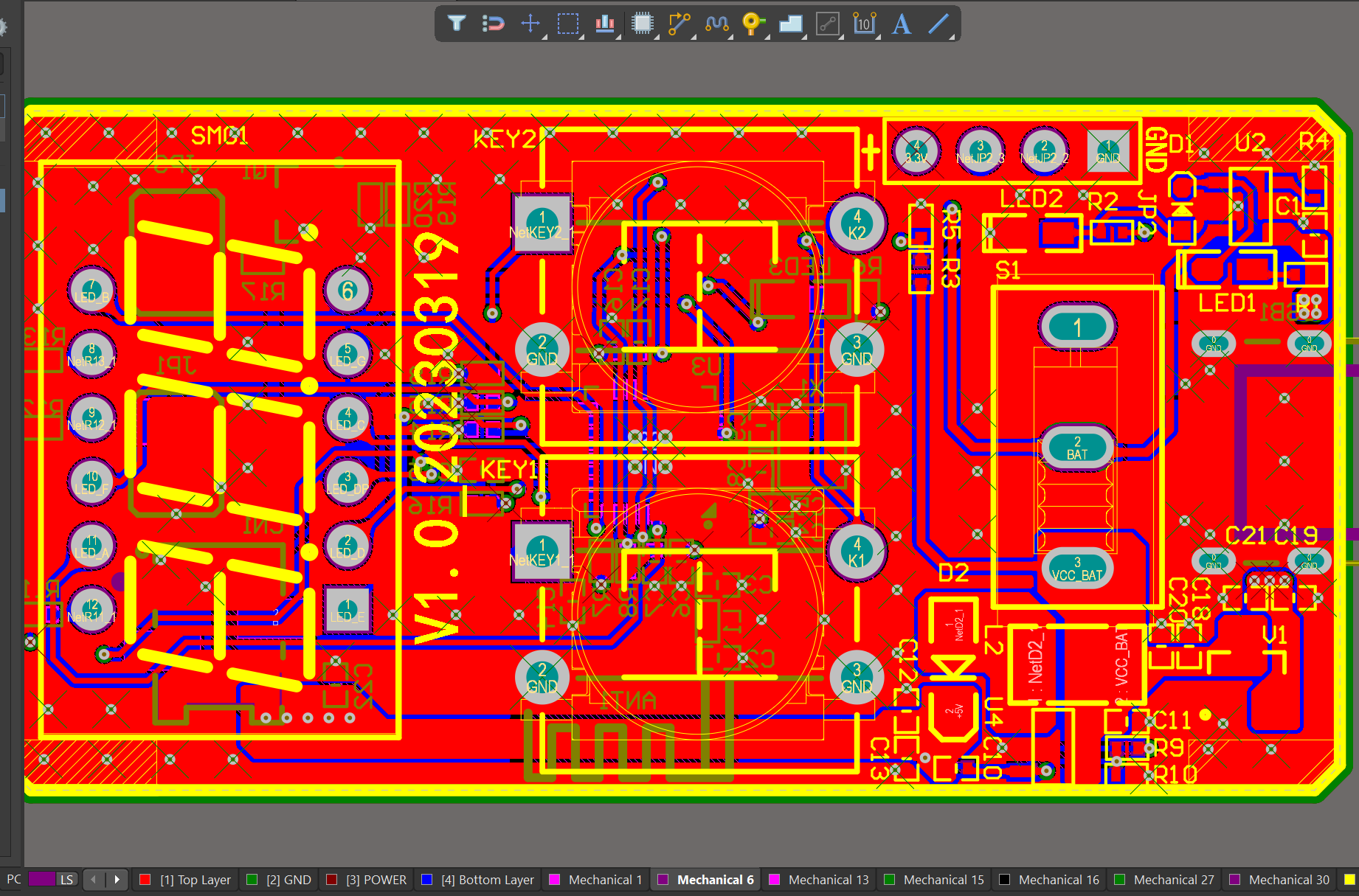
We have rich experience engineer to create a layout using a software platform like Altium Designer. This layout shows you the exact appearance and placement of the components on your board.
Your deliverables are always ahead of schedule and of the highest quality.
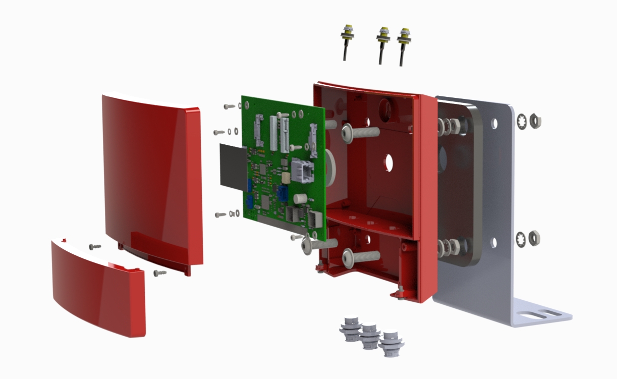
One of our Hardware Design Services is small-batch manufacturing, which allows you to test your idea quickly and verify the functionality of the hardware design and PCB board.

FAQs Guide
2.How important is the trace width and spacing in a PCB design?
3.How does the type of surface finish on a PCB affect its performance?
4.How does the type of solder mask used affect the PCB’s performance?
5.How does the type of signal layers (analog, digital, power) impact the PCB design?
6.How does component placement affect signal integrity in a PCB design?
7.How does the number of layers in a PCB affect its functionality?
8.What is thermal management in PCBs and why is it important?
1.Can a PCB have different levels of flexibility?
We have a wide range of 12v battery charger pcb board customer groups and establishes long -term cooperative relationships with partners.
Yes, a PCB (printed circuit board) can have different levels of flexibility depending on its design and materials used. Some PCBs are rigid and cannot bend or flex at all, while others are designed to be flexible and can bend or twist to a certain degree. There are also PCBs that have a combination of rigid and flexible areas, known as flex-rigid PCBs. The level of flexibility in a PCB is determined by factors such as the type of substrate material, the thickness and number of layers, and the type of circuit design.
2.How important is the trace width and spacing in a PCB design?
Our 12v battery charger pcb board products have competitive and differentiated advantages, and actively promote digital transformation and innovation.
The trace width and spacing in a PCB design are crucial factors that can greatly affect the performance and reliability of the circuit. Here are some reasons why:
1. Current carrying capacity: The trace width determines the amount of current that can flow through the trace without causing excessive heating. If the trace width is too narrow, it can lead to overheating and damage to the circuit.
2. Voltage drop: The trace width also affects the voltage drop across the trace. A narrow trace will have a higher resistance, resulting in a higher voltage drop. This can cause a decrease in the voltage level at the end of the trace, affecting the performance of the circuit.
3. Signal integrity: The spacing between traces is critical for maintaining signal integrity. If the spacing is too narrow, it can lead to crosstalk and interference between signals, resulting in errors and malfunctions in the circuit.
4. Thermal management: The spacing between traces also plays a role in thermal management. Adequate spacing between traces allows for better air circulation, which helps dissipate heat from the circuit. This is especially important for high-power circuits.
5. Manufacturing constraints: The trace width and spacing also need to be considered in the manufacturing process. If the traces are too close together, it can be challenging to etch and inspect the PCB, leading to manufacturing defects.
In summary, the trace width and spacing are critical parameters that need to be carefully considered in PCB design to ensure proper functioning and reliability of the circuit.
3.How does the type of surface finish on a PCB affect its performance?
12v battery charger pcb board is not a product only, but also can help you comes to money-making.
The type of surface finish on a PCB can affect its performance in several ways:
1. Electrical Performance: The surface finish can impact the electrical properties of the PCB, such as impedance, signal integrity, and resistance. A smooth and uniform surface finish can help maintain consistent electrical properties, while a rough or uneven finish can cause signal loss and interference.
2. Solderability: The surface finish plays a crucial role in the solderability of the PCB. A good surface finish should provide a flat and even surface for the components to be soldered onto. A poor surface finish can result in solder defects, such as bridging, voids, and poor wetting, which can affect the reliability of the PCB.
3. Corrosion Resistance: The surface finish can also affect the corrosion resistance of the PCB. A high-quality surface finish can protect the copper traces from oxidation and other environmental factors, ensuring the long-term reliability of the PCB.
4. Assembly Process: Different surface finishes may require different assembly processes, such as the type of solder used or the temperature and time required for reflow. This can affect the overall efficiency and cost of the PCB assembly process.
5. Cost: The type of surface finish can also impact the cost of the PCB. Some surface finishes, such as gold plating, are more expensive than others, such as HASL (Hot Air Solder Leveling). Choosing the right surface finish can help balance the cost and performance requirements of the PCB.
Overall, the surface finish on a PCB can significantly impact its performance, reliability, and cost. It is essential to carefully consider the requirements and choose the most suitable surface finish for the specific application.
4.How does the type of solder mask used affect the PCB’s performance?
We have broad development space in domestic and foreign markets. 12v battery charger pcb boards have great advantages in terms of price, quality, and delivery date.
The type of solder mask used can affect the PCB’s performance in several ways:
1. Insulation: Solder mask is used to insulate the copper traces on a PCB, preventing them from coming into contact with each other and causing a short circuit. The type of solder mask used can affect the level of insulation provided, which can impact the overall reliability and functionality of the PCB.
2. Solderability: Solder mask also plays a crucial role in the soldering process. The type of solder mask used can affect the surface tension and wetting properties of the solder, which can impact the quality of the solder joints and the overall reliability of the PCB.
3. Thermal resistance: Solder mask can also act as a thermal barrier, protecting the PCB from excessive heat. The type of solder mask used can affect the thermal resistance of the PCB, which can impact its ability to dissipate heat and its overall thermal performance.
4. Chemical resistance: Solder mask is also exposed to various chemicals during the PCB manufacturing process, such as flux and cleaning agents. The type of solder mask used can affect its resistance to these chemicals, which can impact the overall durability and reliability of the PCB.
5. Electrical properties: The type of solder mask used can also affect the electrical properties of the PCB, such as its dielectric constant and dissipation factor. These properties can impact the performance of high-frequency circuits and signal integrity.
Overall, the type of solder mask used can have a significant impact on the performance, reliability, and durability of a PCB. It is essential to carefully select the appropriate solder mask for a specific application to ensure optimal performance.
5.How does the type of signal layers (analog, digital, power) impact the PCB design?
As one of the 12v battery charger pcb board market leaders, we are known for innovation and reliability.
The type of signal layers on a PCB (analog, digital, power) can impact the design in several ways:
1. Routing: The type of signal layers will determine how the traces are routed on the PCB. Analog signals require careful routing to minimize noise and interference, while digital signals can tolerate more noise. Power signals require wider traces to handle higher currents.
2. Grounding: Analog signals require a solid ground plane to minimize noise and interference, while digital signals can use a split ground plane to isolate sensitive components. Power signals may require multiple ground planes to handle high currents.
3. Component placement: The type of signal layers can also affect the placement of components on the PCB. Analog components should be placed away from digital components to avoid interference, while power components should be placed close to the power source to minimize voltage drops.
4. Signal integrity: The type of signal layers can also impact the signal integrity of the PCB. Analog signals are more susceptible to noise and interference, so the design must take this into account to ensure accurate signal transmission. Digital signals are less sensitive to noise, but the design must still consider signal integrity to avoid timing issues.
5. EMI/EMC: The type of signal layers can also affect the electromagnetic interference (EMI) and electromagnetic compatibility (EMC) of the PCB. Analog signals are more likely to cause EMI/EMC issues, so the design must include measures to reduce these effects. Digital signals are less likely to cause EMI/EMC issues, but the design must still consider these factors to ensure compliance with regulations.
Overall, the type of signal layers on a PCB can significantly impact the design and must be carefully considered to ensure optimal performance and functionality of the circuit.
6.How does component placement affect signal integrity in a PCB design?
We pay attention to the transformation of intellectual property protection and innovation achievements. Your OEM or ODM order design we have a complete confidentiality system.
Component placement plays a crucial role in determining the signal integrity of a PCB design. The placement of components affects the routing of traces, which in turn affects the impedance, crosstalk, and signal integrity of the PCB.
1. Impedance: The placement of components affects the impedance of the traces. If components are placed too far apart, the traces will be longer, resulting in higher impedance. This can lead to signal reflections and degradation of the signal.
2. Crosstalk: Crosstalk is the interference between two traces on a PCB. The placement of components can affect the distance between traces, which can increase or decrease crosstalk. If components are placed too close together, the crosstalk between traces can increase, leading to signal distortion.
3. Signal routing: The placement of components also affects the routing of traces. If components are placed in a way that requires traces to make sharp turns or cross over each other, it can result in signal degradation. This can be avoided by carefully placing components in a way that allows for smooth and direct routing of traces.
4. Grounding: Proper grounding is essential for maintaining signal integrity. The placement of components can affect the grounding scheme of the PCB. If components are placed too far from the ground plane, it can result in a longer return path for signals, leading to ground bounce and noise.
5. Thermal considerations: The placement of components can also affect the thermal performance of the PCB. If components that generate a lot of heat are placed too close together, it can result in hot spots and affect the performance of the PCB.
To ensure good signal integrity, it is important to carefully consider the placement of components during the PCB design process. Components should be placed in a way that minimizes trace length, reduces crosstalk, allows for direct routing of traces, and ensures proper grounding and thermal management.
7.How does the number of layers in a PCB affect its functionality?
We should have a stable supply chain and logistics capabilities, and provide customers with high -quality, low -priced 12v battery charger pcb board products.
The number of layers in a PCB (Printed Circuit Board) can affect its functionality in several ways:
1. Complexity: The number of layers in a PCB determines the complexity of the circuit design that can be implemented. More layers allow for more components and connections to be included in the design, making it more complex and versatile.
2. Size: A PCB with more layers can be smaller in size compared to a PCB with fewer layers, as it allows for a more compact layout of components and connections. This is especially important in devices with limited space, such as smartphones and wearables.
3. Signal Integrity: The number of layers in a PCB can also affect the signal integrity of the circuit. More layers allow for better routing of signals, reducing the chances of interference and crosstalk between different components.
4. Power Distribution: PCBs with more layers can have dedicated power and ground planes, which help in distributing power evenly across the circuit. This improves the overall performance and stability of the circuit.
5. Cost: The number of layers in a PCB can also affect its cost. More layers mean more materials and manufacturing processes, which can increase the overall cost of the PCB.
6. Thermal Management: PCBs with more layers can have better thermal management, as they allow for the placement of thermal vias and heat sinks to dissipate heat more efficiently. This is important for high-power applications that generate a lot of heat.
In summary, the number of layers in a PCB can significantly impact its functionality, complexity, size, signal integrity, power distribution, cost, and thermal management. Designers must carefully consider the number of layers required for a PCB based on the specific requirements of the circuit and the device it will be used in.
8.What is thermal management in PCBs and why is it important?
We have been working hard to improve service quality and meet customer needs.
Thermal management in PCBs (Printed Circuit Boards) refers to the techniques and strategies used to control and dissipate heat generated by electronic components on the board. It is important because excessive heat can damage components, reduce their performance, and even cause the PCB to fail. Proper thermal management is crucial for ensuring the reliability and longevity of electronic devices.
The electronic components on a PCB generate heat due to the flow of electricity through them. This heat can build up and cause the temperature of the PCB to rise, potentially leading to malfunctions or failures. Thermal management techniques are used to dissipate this heat and maintain the temperature of the PCB within safe operating limits.
There are several methods of thermal management in PCBs, including heat sinks, thermal vias, and thermal pads. Heat sinks are metal components attached to hot components on the PCB to absorb and dissipate heat. Thermal vias are small holes drilled into the PCB to allow heat to escape to the other side of the board. Thermal pads are used to transfer heat from components to the PCB and then to the surrounding air.
Proper thermal management is especially important in high-power and high-density PCBs, where heat generation is more significant. It is also crucial in applications where the PCB is exposed to extreme temperatures or harsh environments. Without effective thermal management, the performance and reliability of electronic devices can be compromised, leading to costly repairs or replacements.
Tags:104 key pcb,16 layer pcb manufacturer

