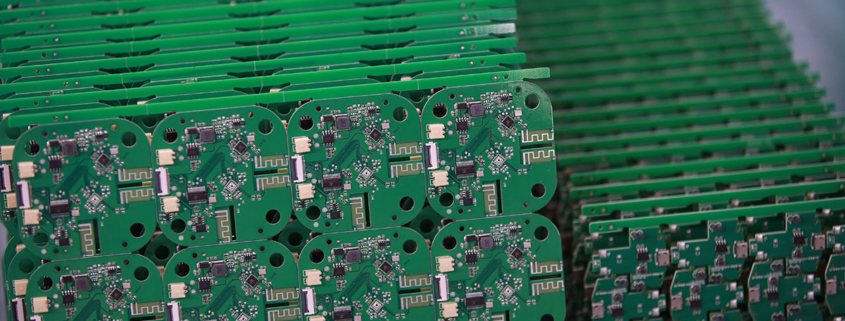
120 mm pcb
MTI is a professional manufacturer of PCB and PCBA , we supply one-stop service. The company’s main services include PCB production, PCB Assembly and electronic materials purchasing, SMT patch, circuit board welding, circuit board plug-in.
Our clientele spans across major continents (Europe,Africa,Oceania)and encompasses various industries, including healthcare,aerospace
| Product name | 120 mm pcb |
| Keyword | assembling circuit boards,108 key keyboard pcb,printed circuit assembly design,pcb manufacturer,printed circuit board assembly pcba |
| Place of Origin | China |
| Board Thickness | 2~3.2mm |
| Applicable Industries | new energy, etc. |
| Service | OEM/ODM manufacturing |
| Certificate | ISO-9001:2015, ISO-14001:2015,ISO-13485:2012.UL/CSA |
| Solder Mask Color | Black |
| Advantage | We keep good quality and competitive price to ensure our customers benefit |
| Sales country | All over the world for example:Saint Lucia,Moldova,Nauru,Switzerland,Jersey,Armenia,Russia,North Korea |
We have rich experience engineer to create a layout using a software platform like Altium Designer. This layout shows you the exact appearance and placement of the components on your board.
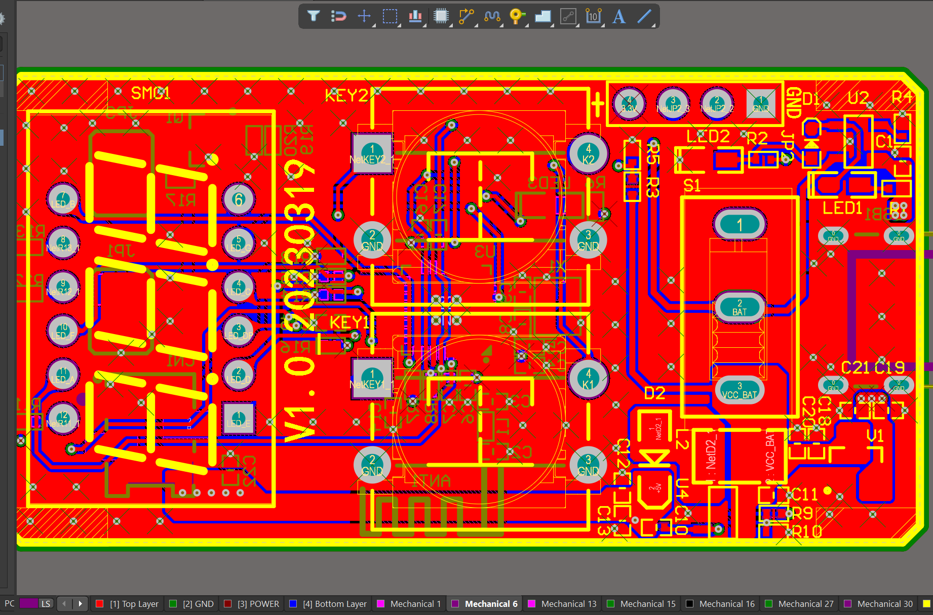
One of our Hardware Design Services is small-batch manufacturing, which allows you to test your idea quickly and verify the functionality of the hardware design and PCB board.

Your deliverables are always ahead of schedule and of the highest quality.
FAQs Guide
2.What is the difference between single-sided and double-sided PCBs?
3.What are the advantages and disadvantages of using a rigid or flexible PCB?
4.What are the different types of through-hole mounting techniques used in PCBs?
5.How do surface mount components differ from through-hole components in a PCB?
6.What is thermal management in PCBs and why is it important?
7.How does the type of surface finish on a PCB affect its performance?
1.What is the minimum distance required between components on a PCB?
We have advanced production equipment and technology to meet the needs of customers, and can provide customers with high quality, low priced 120 mm pcb products.
The minimum distance required between components on a PCB depends on various factors such as the type of components, their size, and the manufacturing process used. Generally, the minimum distance between components is determined by the manufacturer’s design rules and guidelines.
For surface mount components, the minimum distance between components is typically 0.2mm to 0.3mm. This distance is necessary to ensure that the solder paste does not bridge between the pads during the reflow process.
For through-hole components, the minimum distance between components is typically 1mm to 2mm. This distance is necessary to ensure that the components do not interfere with each other during the assembly process.
In high-speed and high-frequency applications, the minimum distance between components may need to be increased to avoid signal interference and crosstalk. In these cases, the manufacturer’s design rules and guidelines should be followed closely.
Overall, the minimum distance between components on a PCB should be determined based on the specific requirements of the design and the capabilities of the manufacturing process.
2.What is the difference between single-sided and double-sided PCBs?
Our mission is to provide customers with the best solutions for 120 mm pcb.
Single-sided PCBs have copper traces and components on only one side of the board, while double-sided PCBs have copper traces and components on both sides of the board. This allows for more complex circuit designs and a higher density of components on a double-sided PCB. Single-sided PCBs are typically used for simpler circuits and are less expensive to manufacture, while double-sided PCBs are used for more complex circuits and are more expensive to manufacture.
3.What are the advantages and disadvantages of using a rigid or flexible PCB?
We have the leading technology and innovation capabilities, and attach importance to employee training and development, and provide promotion opportunities.
Advantages of rigid PCB:
1. Durability: Rigid PCBs are more durable and can withstand higher levels of stress and strain compared to flexible PCBs.
2. Better for high-speed applications: Rigid PCBs are better suited for high-speed applications as they have better signal integrity and lower signal loss.
3. Cost-effective: Rigid PCBs are generally less expensive to manufacture compared to flexible PCBs.
4. Easier to assemble: Rigid PCBs are easier to assemble and can be used with automated assembly processes, making them more efficient for mass production.
5. Higher component density: Rigid PCBs can accommodate a higher number of components and have a higher component density compared to flexible PCBs.
Disadvantages of rigid PCB:
1. Limited flexibility: Rigid PCBs are not flexible and cannot be bent or twisted, making them unsuitable for certain applications.
2. Bulkier: Rigid PCBs are bulkier and take up more space compared to flexible PCBs, which can be a disadvantage in compact electronic devices.
3. Prone to damage: Rigid PCBs are more prone to damage from vibrations and shocks, which can affect their performance.
Advantages of flexible PCB:
1. Flexibility: Flexible PCBs can be bent, twisted, and folded, making them suitable for applications where space is limited or where the PCB needs to conform to a specific shape.
2. Lightweight: Flexible PCBs are lightweight and take up less space compared to rigid PCBs, making them ideal for portable electronic devices.
3. Better for high vibration environments: Flexible PCBs are more resistant to vibrations and shocks, making them suitable for use in high vibration environments.
4. Higher reliability: Flexible PCBs have fewer interconnects and solder joints, reducing the chances of failure and increasing reliability.
Disadvantages of flexible PCB:
1. Higher cost: Flexible PCBs are generally more expensive to manufacture compared to rigid PCBs.
2. Limited component density: Flexible PCBs have a lower component density compared to rigid PCBs, which can limit their use in high-density applications.
3. Difficult to repair: Flexible PCBs are more difficult to repair compared to rigid PCBs, as they require specialized equipment and expertise.
4. Less suitable for high-speed applications: Flexible PCBs have higher signal loss and lower signal integrity compared to rigid PCBs, making them less suitable for high-speed applications.
4.What are the different types of through-hole mounting techniques used in PCBs?
We have flexible production capacity. Whether you are large orders or small orders, you can produce and release goods in a timely manner to meet customer needs.
1. Through-Hole Plating: This is the most common through-hole mounting technique, where the holes in the PCB are plated with a conductive material, usually copper, to create a connection between the layers of the board.
2. Through-Hole Soldering: In this technique, the components are inserted into the plated holes and then soldered to the pads on the opposite side of the board. This provides a strong mechanical connection and good electrical conductivity.
3. Through-Hole Riveting: In this method, the components are inserted into the plated holes and then secured with a rivet or pin. This is commonly used for high-power components or in applications where the board may experience high levels of vibration.
4. Through-Hole Press-Fit: This technique involves inserting the component leads into the plated holes and then pressing them into place using a specialized tool. This provides a strong mechanical connection without the need for soldering.
5. Through-Hole Wave Soldering: In this method, the components are inserted into the plated holes and then passed over a wave of molten solder, which creates a strong solder joint between the component leads and the PCB pads.
6. Through-Hole Reflow Soldering: This technique is similar to wave soldering, but instead of passing over a wave of molten solder, the board is heated in a controlled environment to melt the solder and create a strong joint.
7. Through-Hole Hand Soldering: This is a manual method of soldering where the components are inserted into the plated holes and then soldered by hand using a soldering iron. This is commonly used for small-scale production or for repairs.
8. Through-Hole Pin-in-Paste: This technique involves inserting the component leads into the plated holes and then applying solder paste to the holes before reflow soldering. This provides a strong mechanical connection and good solder joints.
9. Through-Hole Pin-in-Hole: In this method, the component leads are inserted into the plated holes and then bent to form a right angle, creating a secure mechanical connection. This is commonly used for components with large leads, such as electrolytic capacitors.
10. Through-Hole Hand Assembly: This is a manual method of assembly where the components are inserted into the plated holes and then secured with hand tools, such as screws or nuts. This is commonly used for large or heavy components that require additional support.
5.How do surface mount components differ from through-hole components in a PCB?
We pay attention to user experience and product quality, and provide the best product quality and lowest production cost for cooperative customers.
Surface mount components (SMD) and through-hole components (THD) are two different types of electronic components used in printed circuit boards (PCBs). The main difference between them lies in their method of mounting onto the PCB.
1. Mounting Method:
The main difference between SMD and THD components is their mounting method. SMD components are mounted directly onto the surface of the PCB, while THD components are inserted into holes drilled into the PCB and soldered on the other side.
2. Size:
SMD components are generally smaller in size compared to THD components. This is because SMD components do not require leads or pins for mounting, allowing for a more compact design. THD components, on the other hand, have leads or pins that need to be inserted into the PCB, making them larger in size.
3. Space Efficiency:
Due to their smaller size, SMD components allow for a more space-efficient design on the PCB. This is especially important in modern electronic devices where space is limited. THD components take up more space on the PCB due to their larger size and the need for holes to be drilled.
4. Cost:
SMD components are generally more expensive than THD components. This is because SMD components require more advanced manufacturing techniques and equipment, making them costlier to produce.
5. Assembly Process:
The assembly process for SMD components is automated, using pick-and-place machines to accurately place the components onto the PCB. This makes the process faster and more efficient compared to THD components, which require manual insertion and soldering.
6. Electrical Performance:
SMD components have better electrical performance compared to THD components. This is because SMD components have shorter leads, resulting in less parasitic capacitance and inductance, leading to better signal integrity.
In summary, SMD components offer a more compact design, better electrical performance, and a faster assembly process, but at a higher cost. THD components, on the other hand, are larger in size, less expensive, and can handle higher power and voltage ratings. The choice between SMD and THD components depends on the specific requirements of the PCB design and the intended use of the electronic device.
6.What is thermal management in PCBs and why is it important?
We have been working hard to improve service quality and meet customer needs.
Thermal management in PCBs (Printed Circuit Boards) refers to the techniques and strategies used to control and dissipate heat generated by electronic components on the board. It is important because excessive heat can damage components, reduce their performance, and even cause the PCB to fail. Proper thermal management is crucial for ensuring the reliability and longevity of electronic devices.
The electronic components on a PCB generate heat due to the flow of electricity through them. This heat can build up and cause the temperature of the PCB to rise, potentially leading to malfunctions or failures. Thermal management techniques are used to dissipate this heat and maintain the temperature of the PCB within safe operating limits.
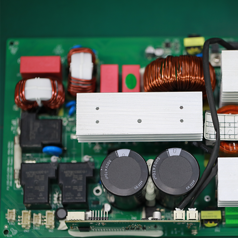
There are several methods of thermal management in PCBs, including heat sinks, thermal vias, and thermal pads. Heat sinks are metal components attached to hot components on the PCB to absorb and dissipate heat. Thermal vias are small holes drilled into the PCB to allow heat to escape to the other side of the board. Thermal pads are used to transfer heat from components to the PCB and then to the surrounding air.
Proper thermal management is especially important in high-power and high-density PCBs, where heat generation is more significant. It is also crucial in applications where the PCB is exposed to extreme temperatures or harsh environments. Without effective thermal management, the performance and reliability of electronic devices can be compromised, leading to costly repairs or replacements.
7.How does the type of surface finish on a PCB affect its performance?
120 mm pcb is not a product only, but also can help you comes to money-making.
The type of surface finish on a PCB can affect its performance in several ways:
1. Electrical Performance: The surface finish can impact the electrical properties of the PCB, such as impedance, signal integrity, and resistance. A smooth and uniform surface finish can help maintain consistent electrical properties, while a rough or uneven finish can cause signal loss and interference.
2. Solderability: The surface finish plays a crucial role in the solderability of the PCB. A good surface finish should provide a flat and even surface for the components to be soldered onto. A poor surface finish can result in solder defects, such as bridging, voids, and poor wetting, which can affect the reliability of the PCB.
3. Corrosion Resistance: The surface finish can also affect the corrosion resistance of the PCB. A high-quality surface finish can protect the copper traces from oxidation and other environmental factors, ensuring the long-term reliability of the PCB.
4. Assembly Process: Different surface finishes may require different assembly processes, such as the type of solder used or the temperature and time required for reflow. This can affect the overall efficiency and cost of the PCB assembly process.
5. Cost: The type of surface finish can also impact the cost of the PCB. Some surface finishes, such as gold plating, are more expensive than others, such as HASL (Hot Air Solder Leveling). Choosing the right surface finish can help balance the cost and performance requirements of the PCB.
Overall, the surface finish on a PCB can significantly impact its performance, reliability, and cost. It is essential to carefully consider the requirements and choose the most suitable surface finish for the specific application.
Tags:printed circuit board assembly suppliers , pcb assembly and production process
