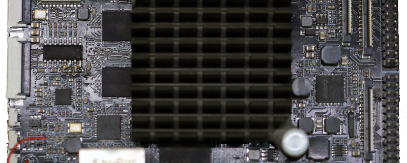
Assembling Circuit Boards
MTI is a high-tech company specializing in PCB manufacturing, PCB assembly and parts procurement services with more than 20 years of experience. We are committed to producing various types of printed circuit boards, mainly including single-sided, double-sided, multi-layer circuit boards, high-precision HDI, flexible boards (FPC), rigid-flex boards (including HDI), metal circuit boards and their SMD plugin.Product line application areas include:power supply.Fast response, strict quality control, best service, and strong technical support export our PCB products to global markets,including,North Korea,Tanzania,Saudi Arabia,Pitcairn Islands,Paracel Islands,Yemen,Guinea-Bissau.
MTI would like to build long and stable business relationship with the customers from all over the world on the basis of mutual benefits and mutual progress;Choose MTI , Drive you Success!
| Product name | Assembling circuit boards |
| Keyword | 2.4ghz pcb antenna,eft pcb,pcb fab,printed circuits assembly,printed circuit board assembly suppliers |
| Place of Origin | China |
| Board Thickness | 2~3.2mm |
| Applicable Industries | power supply, etc. |
| Service | OEM/ODM manufacturing |
| Certificate | ISO-9001:2015, ISO-14001:2015,ISO-13485:2012.UL/CSA |
| Solder Mask Color | White |
| Advantage | We keep good quality and competitive price to ensure our customers benefit |
| Sales country | All over the world for example:North Korea,Tanzania,Saudi Arabia,Pitcairn Islands,Paracel Islands,Yemen,Guinea-Bissau |
We have rich experience engineer to create a layout using a software platform like Altium Designer. This layout shows you the exact appearance and placement of the components on your board.
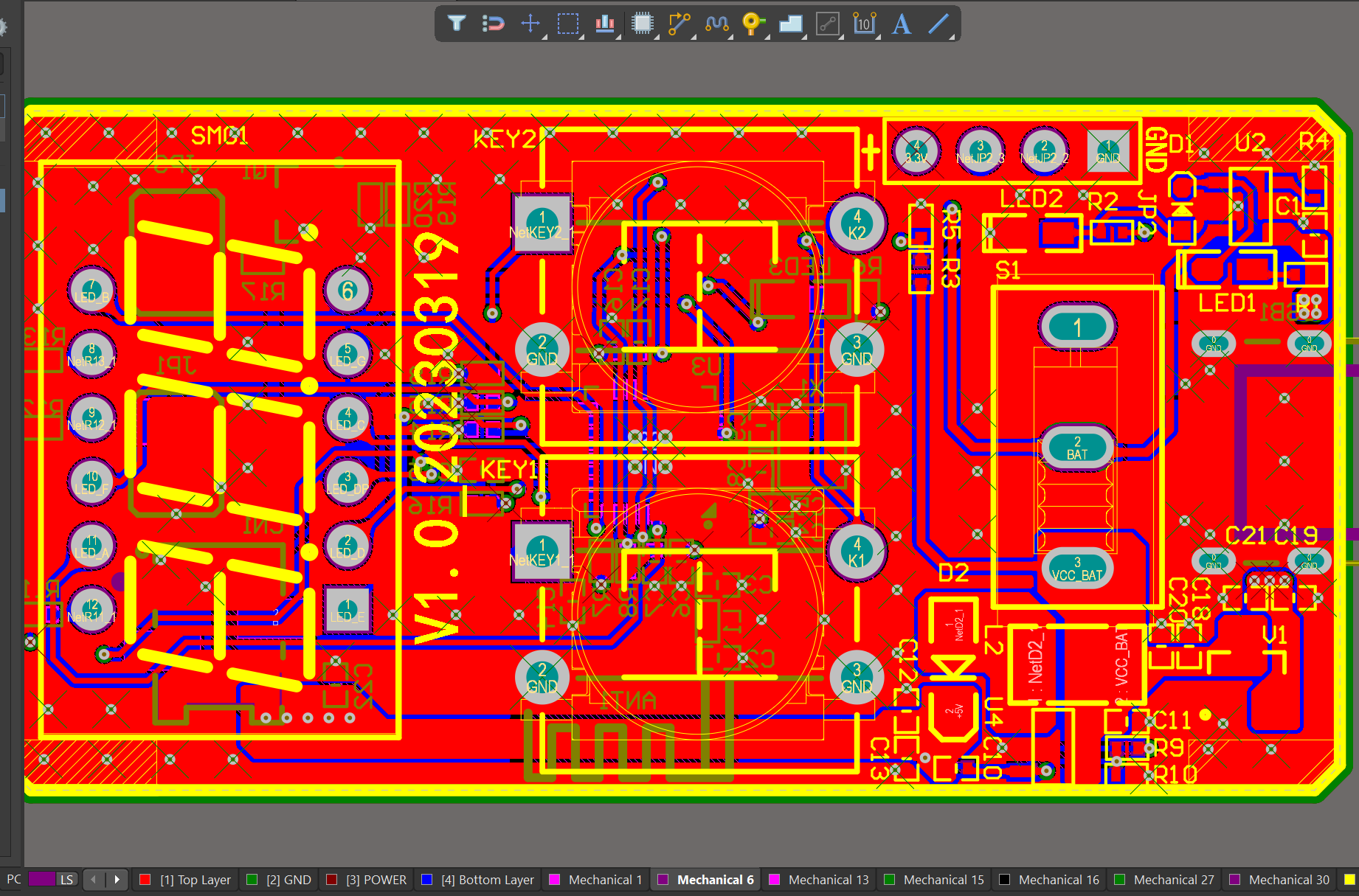
One of our Hardware Design Services is small-batch manufacturing, which allows you to test your idea quickly and verify the functionality of the hardware design and PCB board.

Your deliverables are always ahead of schedule and of the highest quality.
FAQs Guide
2.How do surface mount components differ from through-hole components in a PCB?
3.What is testability in PCB design and how is it achieved?
4.Can PCBs be customized based on specific design requirements?
5.What is the minimum distance required between components on a PCB?
1.What is the maximum current a PCB can handle?
We maintain a certain amount of R&D investment every year and continuously improve operational efficiency to provide better services to our cooperative customers.
The maximum current a PCB can handle depends on various factors such as the thickness and width of the copper traces, the type of material used for the PCB, and the ambient temperature. Generally, a standard PCB can handle currents up to 10-20 amps, while high-power PCBs can handle currents up to 50-100 amps. However, it is always recommended to consult with a PCB manufacturer for specific current handling capabilities for a particular PCB design.
2.How do surface mount components differ from through-hole components in a PCB?
We pay attention to user experience and product quality, and provide the best product quality and lowest production cost for cooperative customers.
Surface mount components (SMD) and through-hole components (THD) are two different types of electronic components used in printed circuit boards (PCBs). The main difference between them lies in their method of mounting onto the PCB.
1. Mounting Method:
The main difference between SMD and THD components is their mounting method. SMD components are mounted directly onto the surface of the PCB, while THD components are inserted into holes drilled into the PCB and soldered on the other side.
2. Size:
SMD components are generally smaller in size compared to THD components. This is because SMD components do not require leads or pins for mounting, allowing for a more compact design. THD components, on the other hand, have leads or pins that need to be inserted into the PCB, making them larger in size.
3. Space Efficiency:
Due to their smaller size, SMD components allow for a more space-efficient design on the PCB. This is especially important in modern electronic devices where space is limited. THD components take up more space on the PCB due to their larger size and the need for holes to be drilled.
4. Cost:
SMD components are generally more expensive than THD components. This is because SMD components require more advanced manufacturing techniques and equipment, making them costlier to produce.
5. Assembly Process:
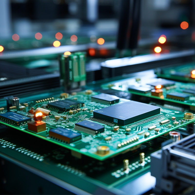
The assembly process for SMD components is automated, using pick-and-place machines to accurately place the components onto the PCB. This makes the process faster and more efficient compared to THD components, which require manual insertion and soldering.
6. Electrical Performance:
SMD components have better electrical performance compared to THD components. This is because SMD components have shorter leads, resulting in less parasitic capacitance and inductance, leading to better signal integrity.
In summary, SMD components offer a more compact design, better electrical performance, and a faster assembly process, but at a higher cost. THD components, on the other hand, are larger in size, less expensive, and can handle higher power and voltage ratings. The choice between SMD and THD components depends on the specific requirements of the PCB design and the intended use of the electronic device.
3.What is testability in PCB design and how is it achieved?
Our assembling circuit boards products undergo strict quality control to ensure customer satisfaction.
Testability in PCB design refers to the ease and accuracy with which a printed circuit board (PCB) can be tested for functionality and performance. It is an important aspect of PCB design as it ensures that any defects or issues with the board can be identified and addressed before it is put into use.
Achieving testability in PCB design involves implementing certain design features and techniques that make it easier to test the board. These include:
1. Design for Test (DFT): This involves designing the PCB with specific test points and access points that allow for easy and accurate testing of different components and circuits.
2. Test Points: These are designated points on the PCB where test probes can be connected to measure voltage, current, and other parameters. Test points should be strategically placed to provide access to critical components and circuits.
3. Test Pads: These are small copper pads on the PCB that are used for attaching test probes. They should be placed close to the corresponding component or circuit for accurate testing.
4. Test Jigs: These are specialized tools used for testing PCBs. They can be custom-made for a specific PCB design and can greatly improve the accuracy and efficiency of testing.
5. Design for Manufacturability (DFM): This involves designing the PCB with manufacturing and testing in mind. This includes using standard components, avoiding complex layouts, and minimizing the number of layers to make testing easier.
6. Design for Debug (DFD): This involves designing the PCB with features that make it easier to identify and troubleshoot any issues that may arise during testing.
Overall, achieving testability in PCB design requires careful planning and consideration of the testing process. By implementing DFT, using test points and pads, and designing for manufacturability and debug, designers can ensure that their PCBs are easily testable and can be quickly and accurately diagnosed for any potential issues.
4.Can PCBs be customized based on specific design requirements?
We have rich industry experience and professional knowledge, and have strong competitiveness in the market.
Yes, PCBs (printed circuit boards) can be customized based on specific design requirements. This is typically done through the use of computer-aided design (CAD) software, which allows for the creation of a custom layout and design for the PCB. The design can be tailored to meet specific size, shape, and functionality requirements, as well as incorporate specific components and features. The customization process may also involve selecting the appropriate materials and manufacturing techniques to ensure the PCB meets the desired specifications.
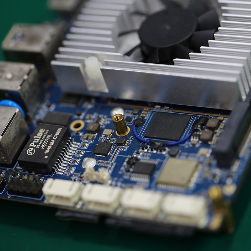
5.What is the minimum distance required between components on a PCB?
We have advanced production equipment and technology to meet the needs of customers, and can provide customers with high quality, low priced assembling circuit boards products.
The minimum distance required between components on a PCB depends on various factors such as the type of components, their size, and the manufacturing process used. Generally, the minimum distance between components is determined by the manufacturer’s design rules and guidelines.
For surface mount components, the minimum distance between components is typically 0.2mm to 0.3mm. This distance is necessary to ensure that the solder paste does not bridge between the pads during the reflow process.
For through-hole components, the minimum distance between components is typically 1mm to 2mm. This distance is necessary to ensure that the components do not interfere with each other during the assembly process.
In high-speed and high-frequency applications, the minimum distance between components may need to be increased to avoid signal interference and crosstalk. In these cases, the manufacturer’s design rules and guidelines should be followed closely.
Overall, the minimum distance between components on a PCB should be determined based on the specific requirements of the design and the capabilities of the manufacturing process.
Tags:printed circuit board assemblies
