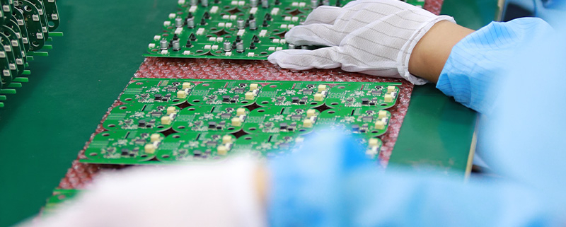
1.6 mm pcb
MTI is a high-tech company specializing in PCB manufacturing, PCB assembly and parts procurement services with more than 20 years of experience. We are committed to producing various types of printed circuit boards, mainly including single-sided, double-sided, multi-layer circuit boards, high-precision HDI, flexible boards (FPC), rigid-flex boards (including HDI), metal circuit boards and their SMD plugin.Product line application areas include:testing instruments.Fast response, strict quality control, best service, and strong technical support export our PCB products to global markets,including,Martinique,Nigeria,Nicaragua,Panama,Bangladesh,India,Burma,Albania.
MTI would like to build long and stable business relationship with the customers from all over the world on the basis of mutual benefits and mutual progress;Choose MTI , Drive you Success!
| Product name | 1.6 mm pcb |
| Keyword | printed circuit board assembly,printed circuit board assembly process |
| Place of Origin | China |
| Board Thickness | 2~3.2mm |
| Applicable Industries | industrial control, etc. |
| Service | OEM/ODM manufacturing |
| Certificate | ISO-9001:2015, ISO-14001:2015,ISO-13485:2012.UL/CSA |
| Solder Mask Color | Red |
| Advantage | We keep good quality and competitive price to ensure our customers benefit |
| Sales country | All over the world for example:Martinique,Nigeria,Nicaragua,Panama,Bangladesh,India,Burma,Albania |
Your deliverables are always ahead of schedule and of the highest quality.
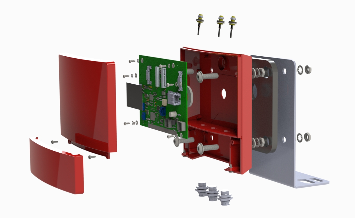
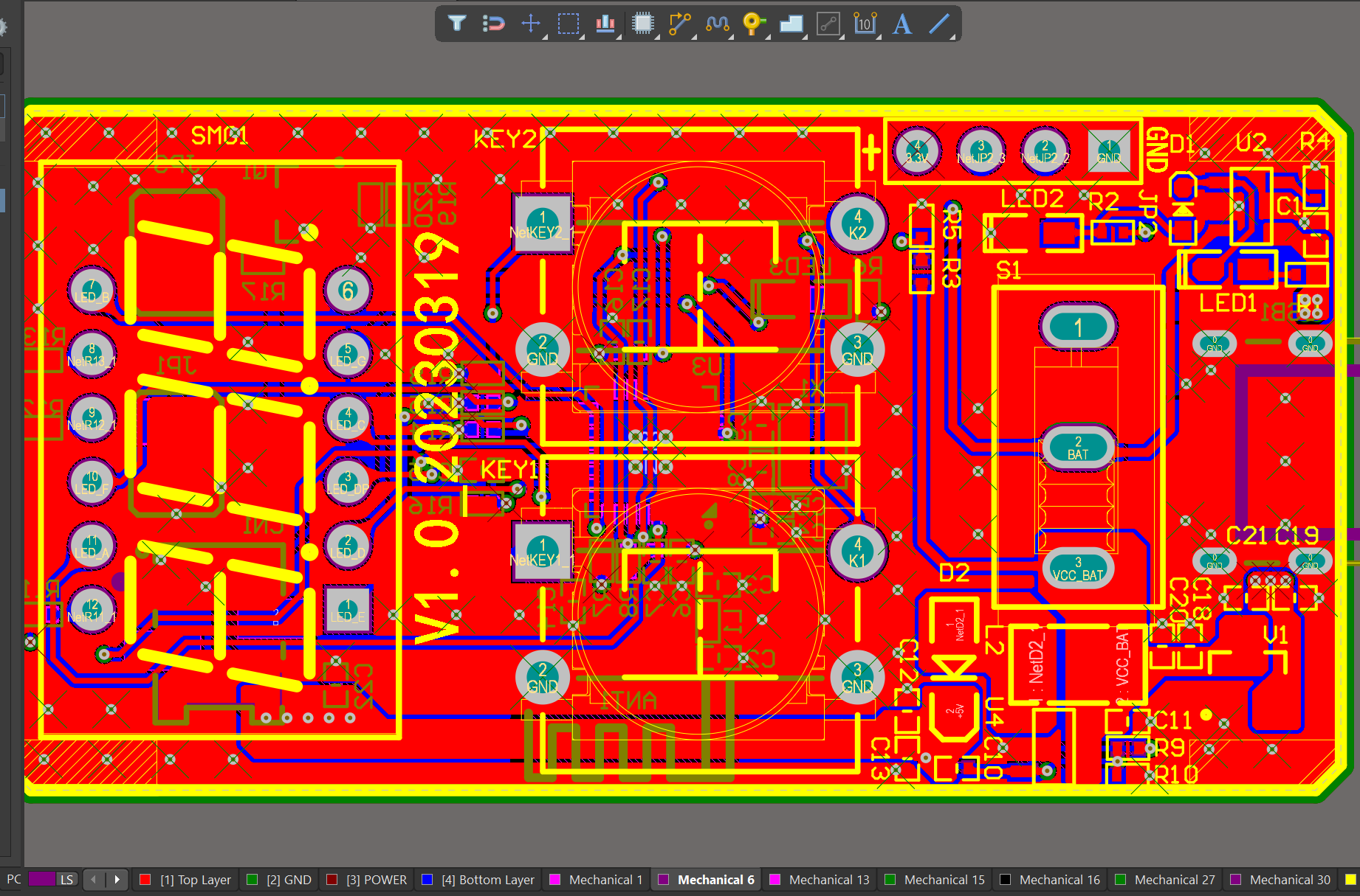
We have rich experience engineer to create a layout using a software platform like Altium Designer. This layout shows you the exact appearance and placement of the components on your board.
One of our Hardware Design Services is small-batch manufacturing, which allows you to test your idea quickly and verify the functionality of the hardware design and PCB board.

FAQs Guide
2.What are the different types of through-hole mounting techniques used in PCBs?
3.What makes a PCB resistant to environmental factors such as moisture and temperature?
4.What is the minimum distance required between components on a PCB?
5.What is impedance control and why is it important in PCBs?
6.Can PCBs be customized based on specific design requirements?
1.How does the type of laminate material used impact the PCB design?
As one of the top 1.6 mm pcb manufacturers in China, we take this very seriously.
The type of laminate material used can impact the 1.6 mm pcb design in several ways:
1. Electrical properties: Different laminate materials have different electrical properties, such as dielectric constant, loss tangent, and insulation resistance. These properties can affect the signal integrity and impedance of the PCB, which can impact the performance of the circuit.
2. Thermal properties: Some laminate materials have better thermal conductivity than others, which can affect the heat dissipation of the PCB. This is especially important for high-power applications where heat management is crucial.
3. Mechanical properties: The mechanical properties of the laminate material, such as stiffness and flexibility, can impact the overall durability and reliability of the PCB. This is important for applications where the PCB may be subjected to physical stress or vibration.
4. Cost: Different laminate materials have different costs, which can impact the overall cost of the PCB. Some materials may be more expensive but offer better performance, while others may be more cost-effective but have lower performance.
5. Manufacturing process: The type of laminate material used can also impact the manufacturing process of the PCB. Some materials may require specialized equipment or processes, which can affect the production time and cost.
6. Compatibility with components: Certain laminate materials may not be compatible with certain components, such as high-frequency components or components that require specific soldering temperatures. This can limit the design options and affect the functionality of the PCB.
Overall, the type of laminate material used can significantly impact the design, performance, and cost of a PCB. It is important to carefully consider the requirements of the circuit and choose a suitable laminate material to ensure optimal performance and reliability.
2.What are the different types of through-hole mounting techniques used in PCBs?
We have flexible production capacity. Whether you are large orders or small orders, you can produce and release goods in a timely manner to meet customer needs.
1. Through-Hole Plating: This is the most common through-hole mounting technique, where the holes in the PCB are plated with a conductive material, usually copper, to create a connection between the layers of the board.
2. Through-Hole Soldering: In this technique, the components are inserted into the plated holes and then soldered to the pads on the opposite side of the board. This provides a strong mechanical connection and good electrical conductivity.
3. Through-Hole Riveting: In this method, the components are inserted into the plated holes and then secured with a rivet or pin. This is commonly used for high-power components or in applications where the board may experience high levels of vibration.
4. Through-Hole Press-Fit: This technique involves inserting the component leads into the plated holes and then pressing them into place using a specialized tool. This provides a strong mechanical connection without the need for soldering.
5. Through-Hole Wave Soldering: In this method, the components are inserted into the plated holes and then passed over a wave of molten solder, which creates a strong solder joint between the component leads and the PCB pads.
6. Through-Hole Reflow Soldering: This technique is similar to wave soldering, but instead of passing over a wave of molten solder, the board is heated in a controlled environment to melt the solder and create a strong joint.
7. Through-Hole Hand Soldering: This is a manual method of soldering where the components are inserted into the plated holes and then soldered by hand using a soldering iron. This is commonly used for small-scale production or for repairs.
8. Through-Hole Pin-in-Paste: This technique involves inserting the component leads into the plated holes and then applying solder paste to the holes before reflow soldering. This provides a strong mechanical connection and good solder joints.
9. Through-Hole Pin-in-Hole: In this method, the component leads are inserted into the plated holes and then bent to form a right angle, creating a secure mechanical connection. This is commonly used for components with large leads, such as electrolytic capacitors.
10. Through-Hole Hand Assembly: This is a manual method of assembly where the components are inserted into the plated holes and then secured with hand tools, such as screws or nuts. This is commonly used for large or heavy components that require additional support.
3.What makes a PCB resistant to environmental factors such as moisture and temperature?
We should perform well in market competition, and the prices of 1.6 mm pcb products have a great competitive advantage.
1. Material Selection: The choice of materials used in the PCB can greatly affect its resistance to environmental factors. Materials such as FR-4, polyimide, and ceramic are known for their high resistance to moisture and temperature.
2. Conformal Coating: Applying a conformal coating to the PCB can provide an additional layer of protection against moisture and temperature. This coating acts as a barrier between the PCB and the environment, preventing any moisture or contaminants from reaching the components.
3. Solder Mask: The solder mask used on the PCB can also play a role in its resistance to environmental factors. A high-quality solder mask can provide a protective layer against moisture and temperature, preventing any damage to the components.
4. Component Placement: Proper placement of components on the PCB can also contribute to its resistance to environmental factors. Components that are sensitive to moisture or temperature should be placed away from areas that are prone to these factors, such as near heat sources or in areas with high humidity.
5. Thermal Management: Adequate thermal management is crucial for maintaining the temperature of the PCB within safe limits. This can be achieved through the use of heat sinks, thermal vias, and proper ventilation.
6. Design Considerations: The design of the PCB can also impact its resistance to environmental factors. Factors such as trace width, spacing, and routing can affect the PCB’s ability to withstand temperature changes and moisture exposure.
7. Testing and Quality Control: Proper testing and quality control measures can ensure that the PCB is built to withstand environmental factors. This includes testing for moisture resistance, thermal cycling, and other environmental stressors.
8. Compliance with Standards: Following industry standards and regulations for PCB design and manufacturing can also contribute to its resistance to environmental factors. These standards often include guidelines for material selection, component placement, and testing procedures.
4.What is the minimum distance required between components on a PCB?
We have advanced production equipment and technology to meet the needs of customers, and can provide customers with high quality, low priced 1.6 mm pcb products.
The minimum distance required between components on a PCB depends on various factors such as the type of components, their size, and the manufacturing process used. Generally, the minimum distance between components is determined by the manufacturer’s design rules and guidelines.
For surface mount components, the minimum distance between components is typically 0.2mm to 0.3mm. This distance is necessary to ensure that the solder paste does not bridge between the pads during the reflow process.
For through-hole components, the minimum distance between components is typically 1mm to 2mm. This distance is necessary to ensure that the components do not interfere with each other during the assembly process.
In high-speed and high-frequency applications, the minimum distance between components may need to be increased to avoid signal interference and crosstalk. In these cases, the manufacturer’s design rules and guidelines should be followed closely.
Overall, the minimum distance between components on a PCB should be determined based on the specific requirements of the design and the capabilities of the manufacturing process.
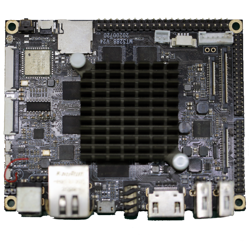
5.What is impedance control and why is it important in PCBs?
We enjoy high authority and influence in the industry and continue to innovate products and service models.
Impedance control is the ability to maintain a consistent electrical impedance throughout a printed circuit board (PCB). It is important in PCBs because it ensures that signals can travel through the board without distortion or loss of quality.
Impedance control is particularly important in high-speed digital and analog circuits, where even small variations in impedance can cause signal reflections and distortions. This can lead to errors in data transmission and affect the overall performance of the circuit.
In addition, impedance control is crucial in ensuring signal integrity and reducing electromagnetic interference (EMI). By maintaining a consistent impedance, the 1.6 mm pcb can effectively filter out unwanted signals and prevent them from interfering with the desired signals.
Overall, impedance control is essential for achieving reliable and high-quality performance in PCBs, especially in complex and sensitive electronic systems. It requires careful design and manufacturing techniques, such as controlled trace widths and spacing, to achieve the desired impedance levels.
6.Can PCBs be customized based on specific design requirements?
We have rich industry experience and professional knowledge, and have strong competitiveness in the market.
Yes, PCBs (printed circuit boards) can be customized based on specific design requirements. This is typically done through the use of computer-aided design (CAD) software, which allows for the creation of a custom layout and design for the PCB. The design can be tailored to meet specific size, shape, and functionality requirements, as well as incorporate specific components and features. The customization process may also involve selecting the appropriate materials and manufacturing techniques to ensure the PCB meets the desired specifications.
Tags:prototype printed circuit board assembly,printed circuits assembly corp,1070 pcb
