2.4 g pcb antenna layout
MTI is a high-tech company specializing in PCB manufacturing, PCB assembly and parts procurement services with more than 20 years of experience. We are committed to producing various types of printed circuit boards, mainly including single-sided, double-sided, multi-layer circuit boards, high-precision HDI, flexible boards (FPC), rigid-flex boards (including HDI), metal circuit boards and their SMD plugin.Product line application areas include:communications.Fast response, strict quality control, best service, and strong technical support export our PCB products to global markets,including,Slovenia,Bosnia and Herzegovina,Germany,Costa Rica,Burkina Faso.
MTI would like to build long and stable business relationship with the customers from all over the world on the basis of mutual benefits and mutual progress;Choose MTI , Drive you Success!
| Product name | 2.4 g pcb antenna layout |
| Keyword | circuit card assembly vs pcb,printed circuit board assembly pcba,flex pcba flexible pcb |
| Place of Origin | China |
| Board Thickness | 1~3.2mm |
| Applicable Industries | communications, etc. |
| Service | OEM/ODM manufacturing |
| Certificate | ISO-9001:2015, ISO-14001:2015,ISO-13485:2012.UL/CSA |
| Solder Mask Color | Green |
| Advantage | We keep good quality and competitive price to ensure our customers benefit |
| Sales country | All over the world for example:Slovenia,Bosnia and Herzegovina,Germany,Costa Rica,Burkina Faso |
One of our Hardware Design Services is small-batch manufacturing, which allows you to test your idea quickly and verify the functionality of the hardware design and PCB board.

Your deliverables are always ahead of schedule and of the highest quality.

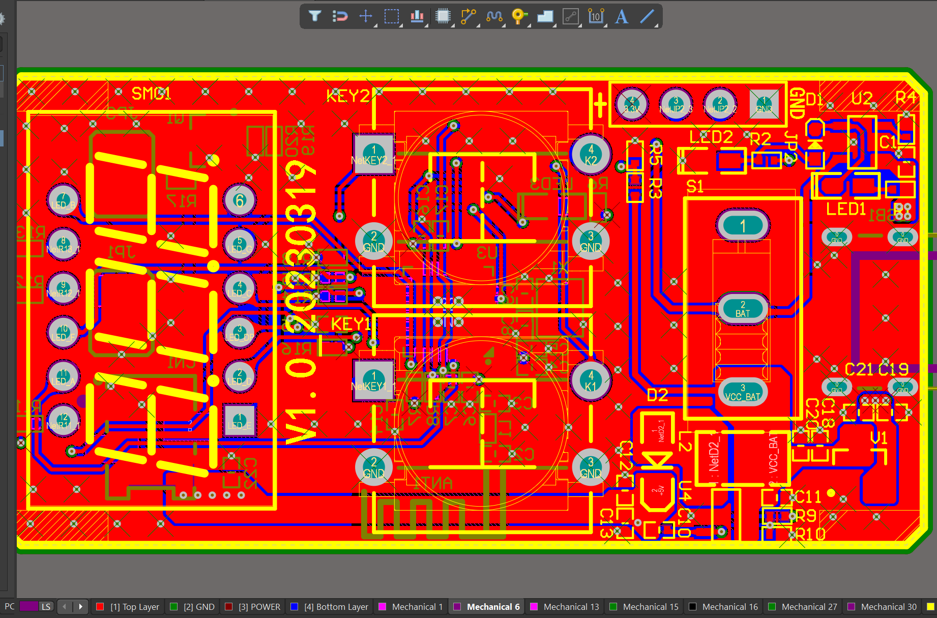
We have rich experience engineer to create a layout using a software platform like Altium Designer. This layout shows you the exact appearance and placement of the components on your board.

FAQs Guide
2.How does component placement affect signal integrity in a PCB design?
3.What is impedance control and why is it important in PCBs?
4.What is the minimum distance required between components on a PCB?
5.How does the type of vias used affect the performance of a PCB?
1.How does the type of signal layers (analog, digital, power) impact the PCB design?
As one of the 2.4 g pcb antenna layout market leaders, we are known for innovation and reliability.
The type of signal layers on a PCB (analog, digital, power) can impact the design in several ways:
1. Routing: The type of signal layers will determine how the traces are routed on the PCB. Analog signals require careful routing to minimize noise and interference, while digital signals can tolerate more noise. Power signals require wider traces to handle higher currents.
2. Grounding: Analog signals require a solid ground plane to minimize noise and interference, while digital signals can use a split ground plane to isolate sensitive components. Power signals may require multiple ground planes to handle high currents.
3. Component placement: The type of signal layers can also affect the placement of components on the PCB. Analog components should be placed away from digital components to avoid interference, while power components should be placed close to the power source to minimize voltage drops.
4. Signal integrity: The type of signal layers can also impact the signal integrity of the PCB. Analog signals are more susceptible to noise and interference, so the design must take this into account to ensure accurate signal transmission. Digital signals are less sensitive to noise, but the design must still consider signal integrity to avoid timing issues.
5. EMI/EMC: The type of signal layers can also affect the electromagnetic interference (EMI) and electromagnetic compatibility (EMC) of the PCB. Analog signals are more likely to cause EMI/EMC issues, so the design must include measures to reduce these effects. Digital signals are less likely to cause EMI/EMC issues, but the design must still consider these factors to ensure compliance with regulations.
Overall, the type of signal layers on a PCB can significantly impact the design and must be carefully considered to ensure optimal performance and functionality of the circuit.
2.How does component placement affect signal integrity in a PCB design?
We pay attention to the transformation of intellectual property protection and innovation achievements. Your OEM or ODM order design we have a complete confidentiality system.
Component placement plays a crucial role in determining the signal integrity of a PCB design. The placement of components affects the routing of traces, which in turn affects the impedance, crosstalk, and signal integrity of the PCB.
1. Impedance: The placement of components affects the impedance of the traces. If components are placed too far apart, the traces will be longer, resulting in higher impedance. This can lead to signal reflections and degradation of the signal.
2. Crosstalk: Crosstalk is the interference between two traces on a PCB. The placement of components can affect the distance between traces, which can increase or decrease crosstalk. If components are placed too close together, the crosstalk between traces can increase, leading to signal distortion.
3. Signal routing: The placement of components also affects the routing of traces. If components are placed in a way that requires traces to make sharp turns or cross over each other, it can result in signal degradation. This can be avoided by carefully placing components in a way that allows for smooth and direct routing of traces.
4. Grounding: Proper grounding is essential for maintaining signal integrity. The placement of components can affect the grounding scheme of the PCB. If components are placed too far from the ground plane, it can result in a longer return path for signals, leading to ground bounce and noise.
5. Thermal considerations: The placement of components can also affect the thermal performance of the PCB. If components that generate a lot of heat are placed too close together, it can result in hot spots and affect the performance of the PCB.
To ensure good signal integrity, it is important to carefully consider the placement of components during the PCB design process. Components should be placed in a way that minimizes trace length, reduces crosstalk, allows for direct routing of traces, and ensures proper grounding and thermal management.
3.What is impedance control and why is it important in PCBs?
We enjoy high authority and influence in the industry and continue to innovate products and service models.
Impedance control is the ability to maintain a consistent electrical impedance throughout a printed circuit board (PCB). It is important in PCBs because it ensures that signals can travel through the board without distortion or loss of quality.
Impedance control is particularly important in high-speed digital and analog circuits, where even small variations in impedance can cause signal reflections and distortions. This can lead to errors in data transmission and affect the overall performance of the circuit.
In addition, impedance control is crucial in ensuring signal integrity and reducing electromagnetic interference (EMI). By maintaining a consistent impedance, the 2.4 g pcb antenna layout can effectively filter out unwanted signals and prevent them from interfering with the desired signals.
Overall, impedance control is essential for achieving reliable and high-quality performance in PCBs, especially in complex and sensitive electronic systems. It requires careful design and manufacturing techniques, such as controlled trace widths and spacing, to achieve the desired impedance levels.

4.What is the minimum distance required between components on a PCB?
We have advanced production equipment and technology to meet the needs of customers, and can provide customers with high quality, low priced 2.4 g pcb antenna layout products.
The minimum distance required between components on a PCB depends on various factors such as the type of components, their size, and the manufacturing process used. Generally, the minimum distance between components is determined by the manufacturer’s design rules and guidelines.
For surface mount components, the minimum distance between components is typically 0.2mm to 0.3mm. This distance is necessary to ensure that the solder paste does not bridge between the pads during the reflow process.
For through-hole components, the minimum distance between components is typically 1mm to 2mm. This distance is necessary to ensure that the components do not interfere with each other during the assembly process.
In high-speed and high-frequency applications, the minimum distance between components may need to be increased to avoid signal interference and crosstalk. In these cases, the manufacturer’s design rules and guidelines should be followed closely.
Overall, the minimum distance between components on a PCB should be determined based on the specific requirements of the design and the capabilities of the manufacturing process.
5.How does the type of vias used affect the performance of a PCB?
Being one of the top 2.4 g pcb antenna layout manufacturers in China, We attach great importance to this detail.
The type of vias used can affect the performance of a PCB in several ways:
1. Signal Integrity: Vias can act as discontinuities in the signal path, causing reflections and signal degradation. The type of via used can impact the impedance and signal integrity of the PCB. For high-speed signals, it is important to use controlled impedance vias to maintain signal integrity.
2. Electrical Performance: The type of via used can also affect the electrical performance of the PCB. For example, through-hole vias have lower resistance and inductance compared to blind or buried vias, which can affect the power delivery and signal transmission on the PCB.
3. Thermal Performance: Vias can also play a role in the thermal performance of a PCB. Through-hole vias can act as thermal vias, allowing heat to dissipate from one layer to another. Blind and buried vias, on the other hand, can trap heat and affect the overall thermal management of the PCB.
4. Manufacturing Cost: The type of via used can also impact the cost of manufacturing the PCB. Blind and buried vias require more complex and expensive processes, while through-hole vias are relatively simpler and cheaper to manufacture.
5. PCB Size and Density: The type of via used can also affect the size and density of the PCB. Blind and buried vias take up less space on the surface of the PCB, allowing for higher density designs. This can be beneficial for smaller and more compact PCBs.
Overall, the type of vias used can have a significant impact on the performance, cost, and design of a PCB. It is important to carefully consider the type of vias needed for a specific application to ensure optimal performance and functionality of the PCB.
Tags:1 layer pcb,eft pcb,10 oz copper pcb


