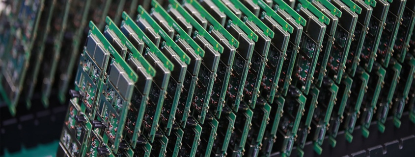
China rigid flex electronic pcba
MTI specializes in turn-key electronics manufacturing manufacturing service, providing comprehensive solutions from product documentation to high-quality product delivery worldwide.
With a wide range, good quality, reasonable prices and stylish designs, our products are extensively used in computer applications.Our products are widely recognized and trusted by users and can meet continuously changing economic and social needs.We welcome new and old customers from all walks of life to contact us for future business relationships and mutual success!
| Product name | China rigid flex electronic pcba |
| Keyword | gh60 pcb,rigid flex electronic pcba,1.6mm pcb stackup,circuit board assemblies,3080 fe pcb |
| Place of Origin | China |
| Board Thickness | 2~3.2mm |
| Applicable Industries | computer applications, etc. |
| Service | OEM/ODM manufacturing |
| Certificate | ISO-9001:2015, ISO-14001:2015,ISO-13485:2012.UL/CSA |
| Solder Mask Color | Blue |
| Advantage | We keep good quality and competitive price to ensure our customers benefit |
| Sales country | All over the world for example:Monaco,Eritrea,Europa Island,Laos,Jersey,Peru,India,Uganda |
One of our Hardware Design Services is small-batch manufacturing, which allows you to test your idea quickly and verify the functionality of the hardware design and PCB board.

Your deliverables are always ahead of schedule and of the highest quality.
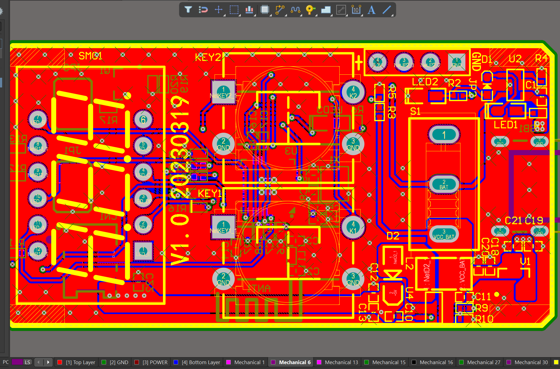
We have rich experience engineer to create a layout using a software platform like Altium Designer. This layout shows you the exact appearance and placement of the components on your board.
FAQs Guide
2.What is impedance control and why is it important in PCBs?
3.How does the type of PCB finish affect its durability and lifespan?
4.What are the factors to consider when choosing the right PCB material for a specific application?
5.What are the different types of through-hole mounting techniques used in PCBs?
6.Can PCBs be designed to withstand high vibration or shock?
7.Can PCBs be customized based on specific design requirements?
1.How does the number of layers in a PCB affect its functionality?
We should have a stable supply chain and logistics capabilities, and provide customers with high -quality, low -priced China rigid flex electronic pcba products.
The number of layers in a PCB (Printed Circuit Board) can affect its functionality in several ways:
1. Complexity: The number of layers in a PCB determines the complexity of the circuit design that can be implemented. More layers allow for more components and connections to be included in the design, making it more complex and versatile.
2. Size: A PCB with more layers can be smaller in size compared to a PCB with fewer layers, as it allows for a more compact layout of components and connections. This is especially important in devices with limited space, such as smartphones and wearables.
3. Signal Integrity: The number of layers in a PCB can also affect the signal integrity of the circuit. More layers allow for better routing of signals, reducing the chances of interference and crosstalk between different components.
4. Power Distribution: PCBs with more layers can have dedicated power and ground planes, which help in distributing power evenly across the circuit. This improves the overall performance and stability of the circuit.
5. Cost: The number of layers in a PCB can also affect its cost. More layers mean more materials and manufacturing processes, which can increase the overall cost of the PCB.
6. Thermal Management: PCBs with more layers can have better thermal management, as they allow for the placement of thermal vias and heat sinks to dissipate heat more efficiently. This is important for high-power applications that generate a lot of heat.
In summary, the number of layers in a PCB can significantly impact its functionality, complexity, size, signal integrity, power distribution, cost, and thermal management. Designers must carefully consider the number of layers required for a PCB based on the specific requirements of the circuit and the device it will be used in.
2.What is impedance control and why is it important in PCBs?
We enjoy high authority and influence in the industry and continue to innovate products and service models.
Impedance control is the ability to maintain a consistent electrical impedance throughout a printed circuit board (PCB). It is important in PCBs because it ensures that signals can travel through the board without distortion or loss of quality.
Impedance control is particularly important in high-speed digital and analog circuits, where even small variations in impedance can cause signal reflections and distortions. This can lead to errors in data transmission and affect the overall performance of the circuit.
In addition, impedance control is crucial in ensuring signal integrity and reducing electromagnetic interference (EMI). By maintaining a consistent impedance, the PCB can effectively filter out unwanted signals and prevent them from interfering with the desired signals.
Overall, impedance control is essential for achieving reliable and high-quality performance in PCBs, especially in complex and sensitive electronic systems. It requires careful design and manufacturing techniques, such as controlled trace widths and spacing, to achieve the desired impedance levels.
3.How does the type of PCB finish affect its durability and lifespan?
I have a comprehensive after -sales service system, which can pay attention to market trends in time and adjust our strategy in a timely manner.
The type of PCB finish can have a significant impact on the durability and lifespan of a China rigid flex electronic pcba. The finish is the final coating applied to the surface of the PCB to protect it from environmental factors and ensure proper functionality. Some common types of PCB finishes include HASL (Hot Air Solder Leveling), ENIG (Electroless Nickel Immersion Gold), and OSP (Organic Solderability Preservative).
1. HASL (Hot Air Solder Leveling):
HASL is a popular and cost-effective finish that involves coating the PCB with a layer of molten solder and then leveling it with hot air. This finish provides good solderability and is suitable for most applications. However, it is not very durable and can be prone to oxidation, which can affect the performance of the PCB over time. HASL finish also has a limited shelf life and may require rework after a certain period.
2. ENIG (Electroless Nickel Immersion Gold):
ENIG is a more advanced and durable finish compared to HASL. It involves depositing a layer of nickel and then a layer of gold on the surface of the PCB. This finish provides excellent corrosion resistance and is suitable for high-reliability applications. ENIG finish also has a longer shelf life and does not require rework as frequently as HASL.
3. OSP (Organic Solderability Preservative):
OSP is a thin organic coating applied to the surface of the PCB to protect it from oxidation. It is a cost-effective finish and provides good solderability. However, OSP finish is not as durable as ENIG and may require rework after a certain period. It is also not suitable for high-temperature applications.
In summary, the type of PCB finish can affect its durability and lifespan in the following ways:
– Corrosion resistance: Finishes like ENIG and OSP provide better corrosion resistance compared to HASL, which can affect the performance and lifespan of the PCB.
– Shelf life: Finishes like ENIG have a longer shelf life compared to HASL, which may require rework after a certain period.
– Solderability: All finishes provide good solderability, but ENIG and OSP are more suitable for high-reliability applications.
– Environmental factors: The type of finish can also affect the PCB’s resistance to environmental factors like humidity, temperature, and chemicals, which can impact its durability and lifespan.
In conclusion, choosing the right type of PCB finish is crucial for ensuring the durability and longevity of the PCB. Factors such as the application, environmental conditions, and budget should be considered when selecting the appropriate finish for a PCB.
4.What are the factors to consider when choosing the right PCB material for a specific application?
We are centered on customers and always pay attention to customers’ needs for China rigid flex electronic pcba products.
1. Electrical properties: The electrical properties of the PCB material, such as dielectric constant, loss tangent, and insulation resistance, should be carefully considered to ensure optimal performance for the specific application.
2. Thermal properties: The thermal conductivity and coefficient of thermal expansion of the PCB material are important factors to consider, especially for applications that require high power or operate in extreme temperatures.
3. Mechanical properties: The mechanical strength, stiffness, and flexibility of the PCB material should be evaluated to ensure it can withstand the physical stresses and strains of the application.
4. Chemical resistance: The PCB material should be resistant to any chemicals or solvents that it may come into contact with during its use.
5. Cost: The cost of the PCB material should be considered, as it can vary significantly depending on the type and quality of the material.
6. Availability: Some PCB materials may be more readily available than others, which can affect production timelines and costs.
7. Manufacturing process: The chosen PCB material should be compatible with the manufacturing process, such as etching, drilling, and plating, to ensure efficient and reliable production.
8. Environmental factors: The application environment, such as humidity, moisture, and exposure to UV light, should be taken into account when selecting a PCB material to ensure it can withstand these conditions.
9. Signal integrity: For high-frequency applications, the PCB material should have low signal loss and good signal integrity to prevent interference and ensure accurate signal transmission.
10. RoHS compliance: If the application requires compliance with environmental regulations, such as the Restriction of Hazardous Substances (RoHS) directive, the PCB material should be chosen accordingly.
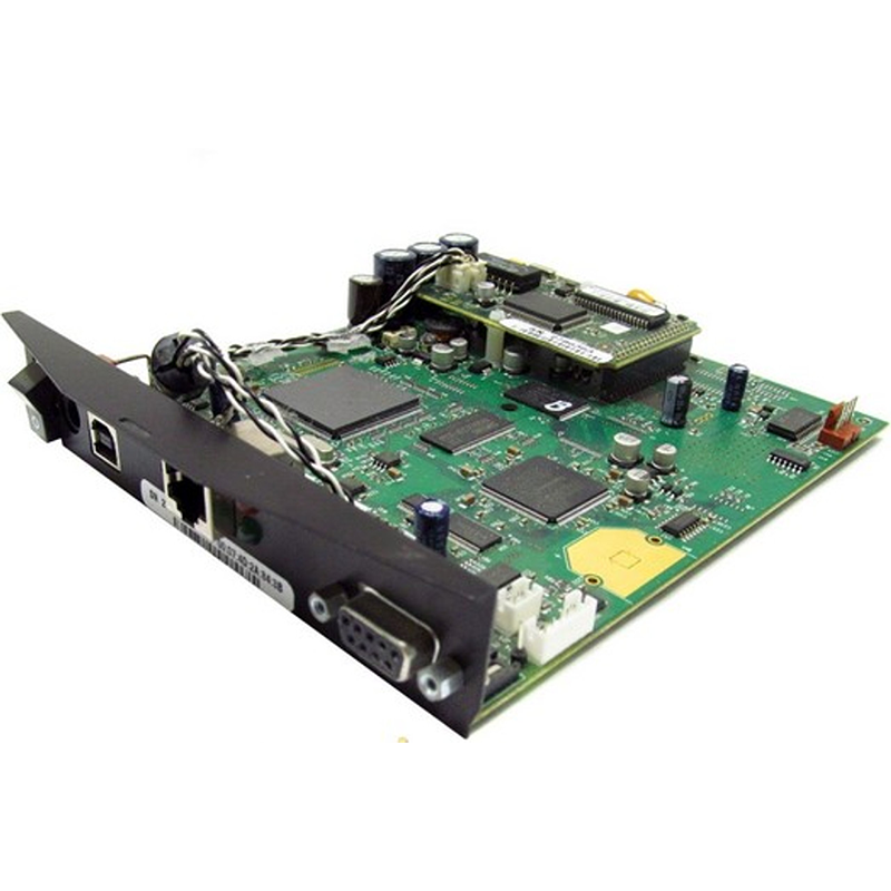
5.What are the different types of through-hole mounting techniques used in PCBs?
We have flexible production capacity. Whether you are large orders or small orders, you can produce and release goods in a timely manner to meet customer needs.
1. Through-Hole Plating: This is the most common through-hole mounting technique, where the holes in the PCB are plated with a conductive material, usually copper, to create a connection between the layers of the board.
2. Through-Hole Soldering: In this technique, the components are inserted into the plated holes and then soldered to the pads on the opposite side of the board. This provides a strong mechanical connection and good electrical conductivity.
3. Through-Hole Riveting: In this method, the components are inserted into the plated holes and then secured with a rivet or pin. This is commonly used for high-power components or in applications where the board may experience high levels of vibration.
4. Through-Hole Press-Fit: This technique involves inserting the component leads into the plated holes and then pressing them into place using a specialized tool. This provides a strong mechanical connection without the need for soldering.
5. Through-Hole Wave Soldering: In this method, the components are inserted into the plated holes and then passed over a wave of molten solder, which creates a strong solder joint between the component leads and the PCB pads.
6. Through-Hole Reflow Soldering: This technique is similar to wave soldering, but instead of passing over a wave of molten solder, the board is heated in a controlled environment to melt the solder and create a strong joint.
7. Through-Hole Hand Soldering: This is a manual method of soldering where the components are inserted into the plated holes and then soldered by hand using a soldering iron. This is commonly used for small-scale production or for repairs.
8. Through-Hole Pin-in-Paste: This technique involves inserting the component leads into the plated holes and then applying solder paste to the holes before reflow soldering. This provides a strong mechanical connection and good solder joints.
9. Through-Hole Pin-in-Hole: In this method, the component leads are inserted into the plated holes and then bent to form a right angle, creating a secure mechanical connection. This is commonly used for components with large leads, such as electrolytic capacitors.
10. Through-Hole Hand Assembly: This is a manual method of assembly where the components are inserted into the plated holes and then secured with hand tools, such as screws or nuts. This is commonly used for large or heavy components that require additional support.
6.Can PCBs be designed to withstand high vibration or shock?
We have established long-term and stable partnerships with our suppliers, so we have great advantages in price and cost and quality assurance.
Yes, PCBs can be designed to withstand high vibration or shock by incorporating certain design features and using appropriate materials. Some ways to make a PCB more resistant to vibration and shock include:
1. Using a thicker and more rigid PCB substrate material, such as FR-4 or ceramic, to provide better structural support and reduce flexing.
2. Adding additional support structures, such as mounting holes or stiffeners, to secure the PCB to the chassis or enclosure.
3. Using smaller and more compact components to reduce the overall weight and size of the PCB, which can help minimize the effects of vibration.
4. Using shock-absorbing materials, such as rubber or foam, between the PCB and the mounting surface to absorb and dampen vibrations.
5. Designing the PCB layout to minimize the length and number of traces and vias, which can reduce the risk of mechanical stress and failure.
6. Using surface mount technology (SMT) components instead of through-hole components, as they are less prone to damage from vibration.
7. Incorporating conformal coating or potting materials to protect the PCB and components from moisture and mechanical stress.
It is important to consider the specific requirements and environment in which the PCB will be used when designing for high vibration or shock resistance. Consulting with a PCB design expert can also help ensure that the PCB is properly designed to withstand these conditions.
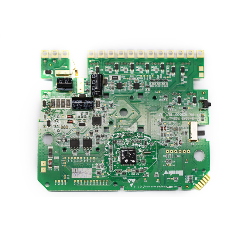
7.Can PCBs be customized based on specific design requirements?
We have rich industry experience and professional knowledge, and have strong competitiveness in the market.
Yes, PCBs (printed circuit boards) can be customized based on specific design requirements. This is typically done through the use of computer-aided design (CAD) software, which allows for the creation of a custom layout and design for the PCB. The design can be tailored to meet specific size, shape, and functionality requirements, as well as incorporate specific components and features. The customization process may also involve selecting the appropriate materials and manufacturing techniques to ensure the PCB meets the desired specifications.
Tags:1.2 mm pcb,1073 pcb
