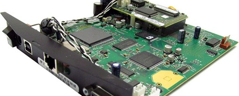
1080 pcb
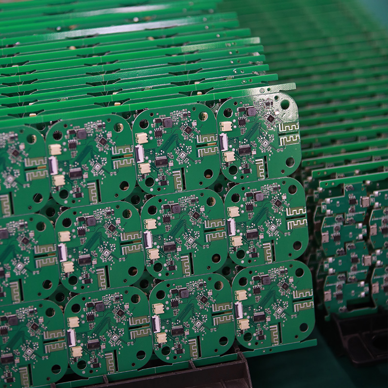
MTI is a professional manufacturer of PCB and PCBA , we supply one-stop service. The company’s main services include PCB production, PCB Assembly and electronic materials purchasing, SMT patch, circuit board welding, circuit board plug-in,1080 pcb.
Our clientele spans across major continents (Europe,Africa,America)and encompasses various industries, including healthcare,computers and peripherals
| Product name | 1080 pcb |
| Keyword | 2.4 ghz yagi pcb antenna,printed circuit assembly design,1.27 mm pcb,china printed circuit board assembly,circuit boards assembly |
| Place of Origin | China |
| Board Thickness | 2~3.2mm |
| Applicable Industries | industrial control, etc. |
| Service | OEM/ODM manufacturing |
| Certificate | ISO-9001:2015, ISO-14001:2015,ISO-13485:2012.UL/CSA |
| Solder Mask Color | Red |
| Advantage | We keep good quality and competitive price to ensure our customers benefit |
| Sales country | All over the world for example:Iran,Malaysia,Bermuda,Central African Republic,Denmark,Chile,Wallis and Futuna,Liberia,Greece |
Your deliverables are always ahead of schedule and of the highest quality.
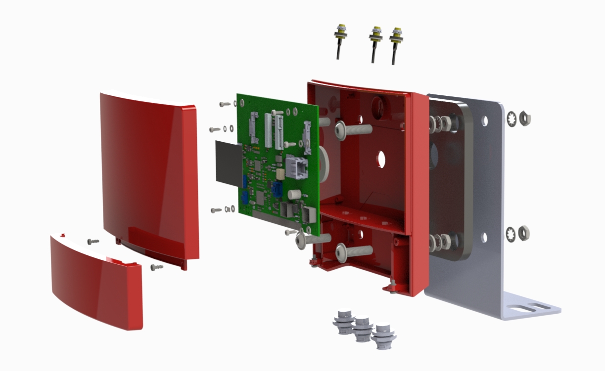
One of our Hardware Design Services is small-batch manufacturing, which allows you to test your idea quickly and verify the functionality of the hardware design and PCB board.

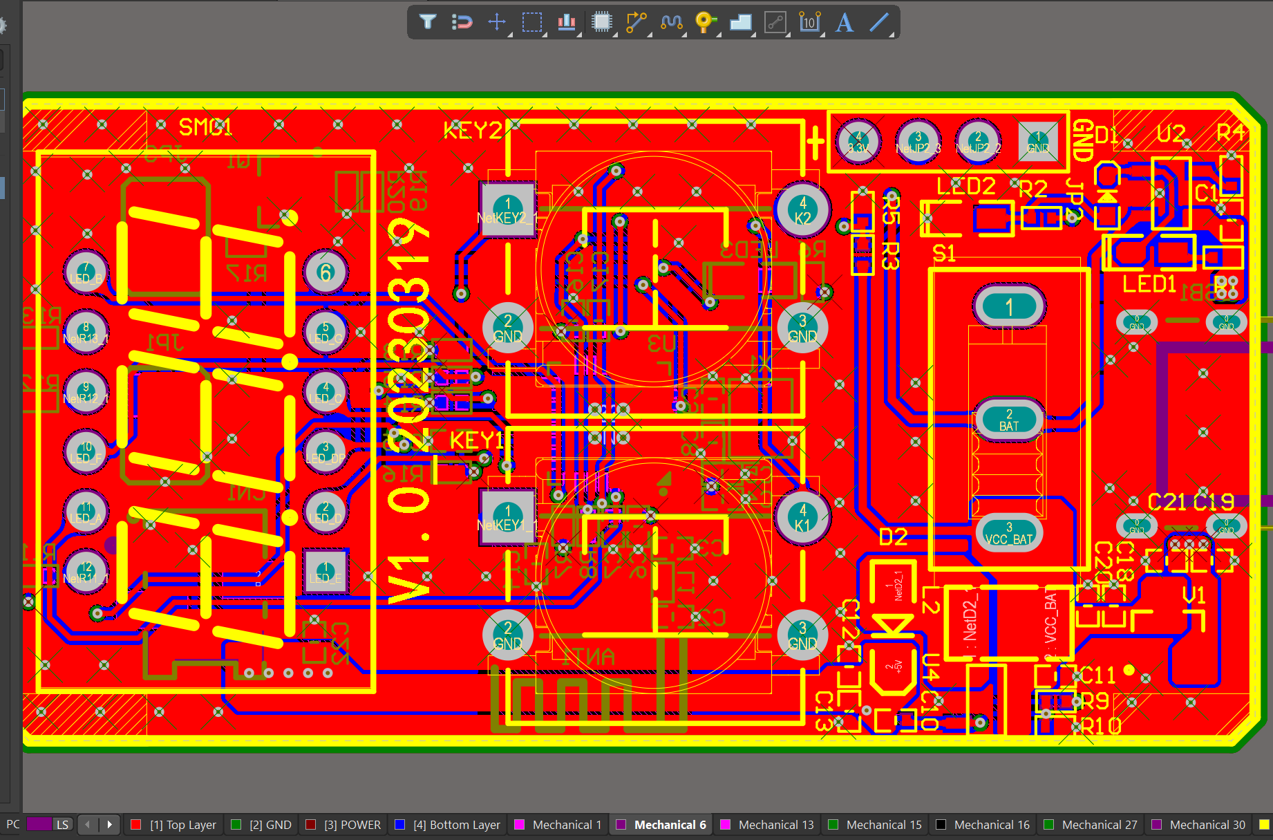
We have rich experience engineer to create a layout using a software platform like Altium Designer. This layout shows you the exact appearance and placement of the components on your board.
FAQs Guide
2.How do PCBs support the integration of different electronic components?
3.What is the difference between single-sided and double-sided PCBs?
4.Can PCBs have different shapes and sizes?
5.How does the type of solder mask used affect the PCB’s performance?
6.What are the different types of through-hole mounting techniques used in PCBs?
1.Is it possible to have different components on each side of a PCB?
We focus on innovation and continuous improvement to maintain a competitive advantage.
Yes, it is possible to have different components on each side of a PCB. This is known as a double-sided PCB or a two-layer PCB. The components on each side can be connected through vias, which are small holes drilled through the PCB that allow for electrical connections between the layers. This allows for more compact and complex circuit designs. However, it also adds complexity to the manufacturing process and may increase the cost of the PCB.
2.How do PCBs support the integration of different electronic components?
We actively participate in the 1080 pcb industry associations and organization activities. The corporate social responsibility performed well, and the focus of brand building and promotion.
PCBs (Printed Circuit Boards) are essential for the integration of different electronic components in electronic devices. They provide a platform for connecting and supporting the various components, allowing them to work together seamlessly. Here are some ways in which PCBs support the integration of different electronic components:
1. Electrical connections: PCBs have a network of copper traces that connect the different electronic components on the board. These traces act as conductors, allowing electricity to flow between the components and enabling them to communicate and work together.
2. Mounting surface: PCBs provide a stable and secure mounting surface for electronic components. The components are soldered onto the board, ensuring that they are firmly attached and will not move or become loose during operation.
3. Space-saving: PCBs are designed to be compact and space-saving, allowing for the integration of multiple components on a single board. This is especially useful in small electronic devices where space is limited.
4. Customization: PCBs can be customized to accommodate different types and sizes of electronic components. This allows for flexibility in design and the integration of a wide range of components, making it easier to create complex electronic devices.
5. Signal routing: PCBs have multiple layers, with each layer dedicated to a specific function. This allows for efficient routing of signals between components, reducing interference and ensuring that the components can communicate effectively.
6. Power distribution: PCBs have dedicated power planes that distribute power to the different components on the board. This ensures that each component receives the required amount of power, preventing damage and ensuring proper functioning.
7. Thermal management: PCBs also play a crucial role in managing the heat generated by electronic components. They have copper layers that act as heat sinks, dissipating heat and preventing the components from overheating.
In summary, PCBs provide a robust and efficient platform for integrating different electronic components. They enable the components to work together seamlessly, ensuring the proper functioning of electronic devices.
3.What is the difference between single-sided and double-sided PCBs?
Our mission is to provide customers with the best solutions for 1080 pcb.
Single-sided PCBs have copper traces and components on only one side of the board, while double-sided PCBs have copper traces and components on both sides of the board. This allows for more complex circuit designs and a higher density of components on a double-sided PCB. Single-sided PCBs are typically used for simpler circuits and are less expensive to manufacture, while double-sided PCBs are used for more complex circuits and are more expensive to manufacture.
4.Can PCBs have different shapes and sizes?
Our company has many years of 1080 pcb experience and expertise.
Yes, PCBs (printed circuit boards) can have different shapes and sizes depending on the specific design and purpose of the circuit. They can range from small and compact to large and complex, and can be rectangular, circular, or even irregularly shaped. The shape and size of a PCB is determined by the layout of the components and the desired functionality of the circuit.
5.How does the type of solder mask used affect the PCB’s performance?
We have broad development space in domestic and foreign markets. 1080 pcbs have great advantages in terms of price, quality, and delivery date.
The type of solder mask used can affect the PCB’s performance in several ways:
1. Insulation: Solder mask is used to insulate the copper traces on a PCB, preventing them from coming into contact with each other and causing a short circuit. The type of solder mask used can affect the level of insulation provided, which can impact the overall reliability and functionality of the PCB.
2. Solderability: Solder mask also plays a crucial role in the soldering process. The type of solder mask used can affect the surface tension and wetting properties of the solder, which can impact the quality of the solder joints and the overall reliability of the PCB.
3. Thermal resistance: Solder mask can also act as a thermal barrier, protecting the PCB from excessive heat. The type of solder mask used can affect the thermal resistance of the PCB, which can impact its ability to dissipate heat and its overall thermal performance.
4. Chemical resistance: Solder mask is also exposed to various chemicals during the PCB manufacturing process, such as flux and cleaning agents. The type of solder mask used can affect its resistance to these chemicals, which can impact the overall durability and reliability of the PCB.
5. Electrical properties: The type of solder mask used can also affect the electrical properties of the PCB, such as its dielectric constant and dissipation factor. These properties can impact the performance of high-frequency circuits and signal integrity.
Overall, the type of solder mask used can have a significant impact on the performance, reliability, and durability of a PCB. It is essential to carefully select the appropriate solder mask for a specific application to ensure optimal performance.
6.What are the different types of through-hole mounting techniques used in PCBs?
We have flexible production capacity. Whether you are large orders or small orders, you can produce and release goods in a timely manner to meet customer needs.
1. Through-Hole Plating: This is the most common through-hole mounting technique, where the holes in the PCB are plated with a conductive material, usually copper, to create a connection between the layers of the board.
2. Through-Hole Soldering: In this technique, the components are inserted into the plated holes and then soldered to the pads on the opposite side of the board. This provides a strong mechanical connection and good electrical conductivity.
3. Through-Hole Riveting: In this method, the components are inserted into the plated holes and then secured with a rivet or pin. This is commonly used for high-power components or in applications where the board may experience high levels of vibration.
4. Through-Hole Press-Fit: This technique involves inserting the component leads into the plated holes and then pressing them into place using a specialized tool. This provides a strong mechanical connection without the need for soldering.
5. Through-Hole Wave Soldering: In this method, the components are inserted into the plated holes and then passed over a wave of molten solder, which creates a strong solder joint between the component leads and the PCB pads.
6. Through-Hole Reflow Soldering: This technique is similar to wave soldering, but instead of passing over a wave of molten solder, the board is heated in a controlled environment to melt the solder and create a strong joint.
7. Through-Hole Hand Soldering: This is a manual method of soldering where the components are inserted into the plated holes and then soldered by hand using a soldering iron. This is commonly used for small-scale production or for repairs.
8. Through-Hole Pin-in-Paste: This technique involves inserting the component leads into the plated holes and then applying solder paste to the holes before reflow soldering. This provides a strong mechanical connection and good solder joints.
9. Through-Hole Pin-in-Hole: In this method, the component leads are inserted into the plated holes and then bent to form a right angle, creating a secure mechanical connection. This is commonly used for components with large leads, such as electrolytic capacitors.
10. Through-Hole Hand Assembly: This is a manual method of assembly where the components are inserted into the plated holes and then secured with hand tools, such as screws or nuts. This is commonly used for large or heavy components that require additional support.
Tags:1.6mm pcb stackup,3080 pcb,3018 cnc pcb
