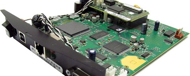
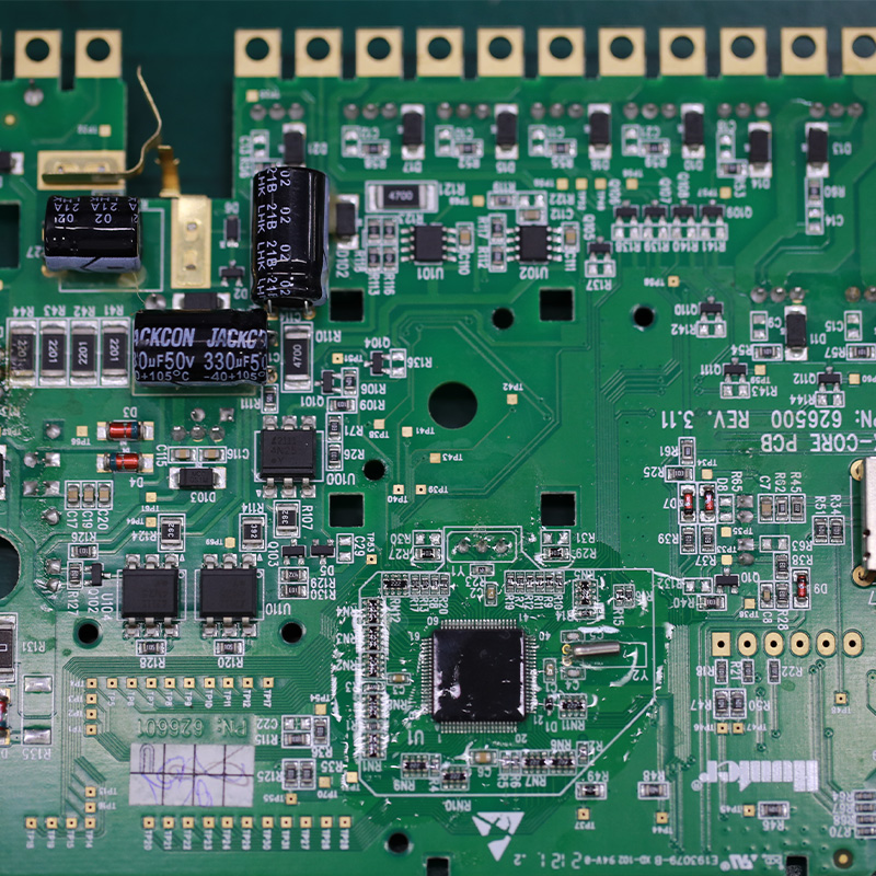
Flexible pcb board
MTI is a professional manufacturer of PCB and PCBA , we supply one-stop service. The company’s main services include PCB production, Flexible pcb board, PCB Assembly, and electronic materials purchasing, SMT patch, circuit board welding, circuit board plug-in.
Our clientele spans across major continents (Asia,Oceania,Europe)and encompasses various industries, including healthcare,medical
| Product name | flexible pcb board |
| Keyword | 100w amplifier pcb,printed circuits assembly corporation,gh60 pcb,16 layer pcb manufacturer,printed circuits assembly corp |
| Place of Origin | China |
| Board Thickness | 1~3.2mm |
| Applicable Industries | medical, etc. |
| Service | OEM/ODM manufacturing |
| Certificate | ISO-9001:2015, ISO-14001:2015,ISO-13485:2012.UL/CSA |
| Solder Mask Color | Blue |
| Advantage | We keep good quality and competitive price to ensure our customers benefit |
| Sales country | All over the world for example:Cape Verde,Sao Tome and Principe,Mozambique,Dominican Republic,Russia,Brunei,Bhutan,Mauritania |
Your deliverables are always ahead of schedule and of the highest quality.
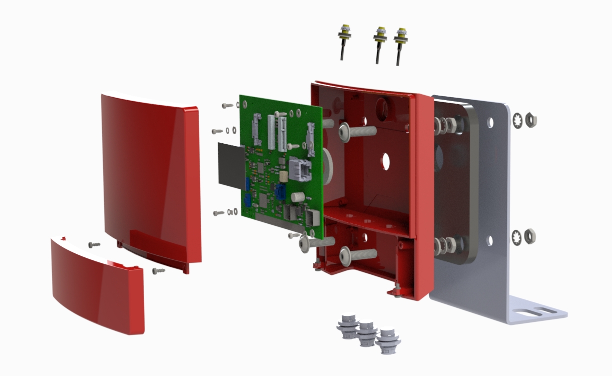
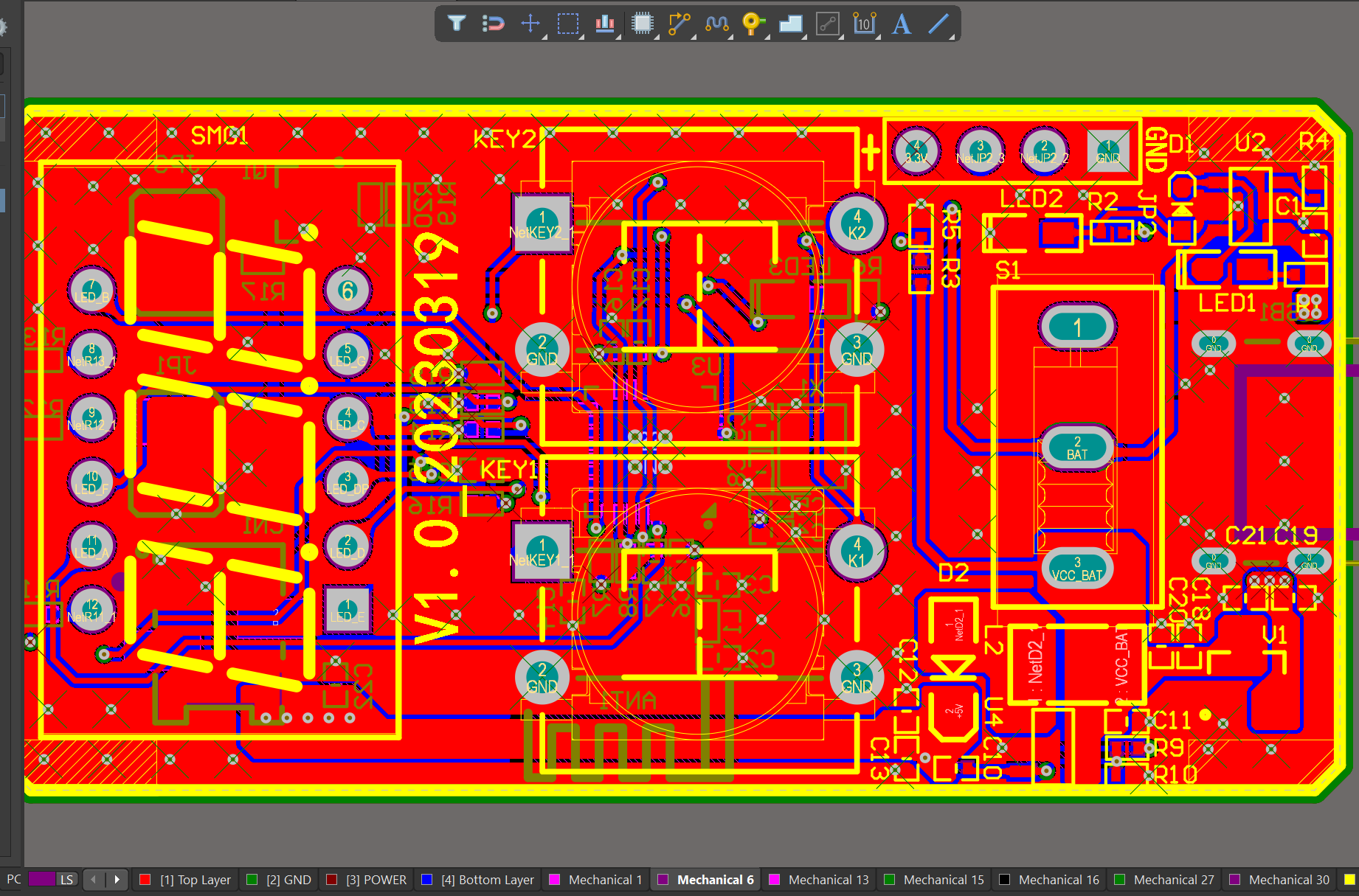
We have rich experience engineer to create a layout using a software platform like Altium Designer. This layout shows you the exact appearance and placement of the components on your board.
One of our Hardware Design Services is small-batch manufacturing, which allows you to test your idea quickly and verify the functionality of the hardware design and PCB board.

FAQs Guide
2.Can PCBs be designed with high-speed and high-frequency applications in mind?
3.What materials are commonly used to make PCBs?
4.Can PCBs have different shapes and sizes?
5.What is the maximum current a PCB can handle?
6.How do PCBs handle overcurrent and short circuits?
7.What is impedance control and why is it important in PCBs?
8.How does the type of PCB connection (wired or wireless) impact its design and features?
1.What are the factors to consider when choosing the right PCB material for a specific application?
We are centered on customers and always pay attention to customers’ needs for flexible pcb board products.
1. Electrical properties: The electrical properties of the PCB material, such as dielectric constant, loss tangent, and insulation resistance, should be carefully considered to ensure optimal performance for the specific application.
2. Thermal properties: The thermal conductivity and coefficient of thermal expansion of the PCB material are important factors to consider, especially for applications that require high power or operate in extreme temperatures.
3. Mechanical properties: The mechanical strength, stiffness, and flexibility of the PCB material should be evaluated to ensure it can withstand the physical stresses and strains of the application.
4. Chemical resistance: The PCB material should be resistant to any chemicals or solvents that it may come into contact with during its use.
5. Cost: The cost of the PCB material should be considered, as it can vary significantly depending on the type and quality of the material.
6. Availability: Some PCB materials may be more readily available than others, which can affect production timelines and costs.
7. Manufacturing process: The chosen PCB material should be compatible with the manufacturing process, such as etching, drilling, and plating, to ensure efficient and reliable production.
8. Environmental factors: The application environment, such as humidity, moisture, and exposure to UV light, should be taken into account when selecting a PCB material to ensure it can withstand these conditions.
9. Signal integrity: For high-frequency applications, the PCB material should have low signal loss and good signal integrity to prevent interference and ensure accurate signal transmission.
10. RoHS compliance: If the application requires compliance with environmental regulations, such as the Restriction of Hazardous Substances (RoHS) directive, the PCB material should be chosen accordingly.
2.Can PCBs be designed with high-speed and high-frequency applications in mind?
We attach importance to the innovation ability and team spirit of employees, have advanced R & D facilities and laboratories, and have a good quality management system.
Yes, PCBs can be designed with high-speed and high-frequency applications in mind. This involves careful consideration of the layout, trace routing, and component placement to minimize signal loss and interference. Specialized materials and techniques, such as controlled impedance routing and differential pairs, can also be used to improve signal integrity and reduce noise. Additionally, the use of advanced simulation and analysis tools can help optimize the design for high-speed and high-frequency performance.
3.What materials are commonly used to make PCBs?
We have advantages in marketing and channel expansion. Suppliers have established good cooperative relations, continuously improved workflows, improved efficiency and productivity, and provided customers with high -quality products and services.
1. Copper: Copper is the most commonly used material for PCBs. It is used as the conductive layer for the circuit traces and pads.
2. FR4: FR4 is a type of fiberglass-reinforced epoxy laminate that is used as the base material for most PCBs. It provides good mechanical strength and insulation properties.
3. Solder mask: Solder mask is a layer of polymer that is applied over the copper traces to protect them from oxidation and to prevent solder bridges during assembly.
4. Silkscreen: Silkscreen is a layer of ink that is printed on top of the solder mask to provide component labels, reference designators, and other information.
5. Tin/lead or lead-free solder: Solder is used to attach components to the PCB and to create electrical connections between them.
6. Gold: Gold is used for plating the contact pads and vias on the PCB, as it provides good conductivity and corrosion resistance.
7. Silver: Silver is sometimes used as an alternative to gold for plating contact pads and vias, as it is cheaper but still provides good conductivity.
8. Nickel: Nickel is used as a barrier layer between the copper and gold or silver plating to prevent them from diffusing into each other.
9. Epoxy resin: Epoxy resin is used as an adhesive to bond the layers of the PCB together.
10. Ceramic: Ceramic materials are used for specialized PCBs that require high thermal conductivity and insulation properties, such as in high-power applications.
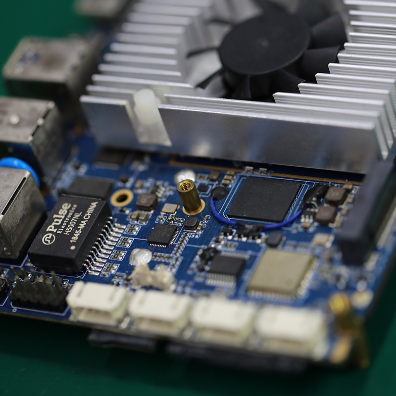
4.Can PCBs have different shapes and sizes?
Our company has many years of flexible pcb board experience and expertise.
Yes, PCBs (printed circuit boards) can have different shapes and sizes depending on the specific design and purpose of the circuit. They can range from small and compact to large and complex, and can be rectangular, circular, or even irregularly shaped. The shape and size of a PCB is determined by the layout of the components and the desired functionality of the circuit.
5.What is the maximum current a PCB can handle?
We maintain a certain amount of R&D investment every year and continuously improve operational efficiency to provide better services to our cooperative customers.
The maximum current a PCB can handle depends on various factors such as the thickness and width of the copper traces, the type of material used for the PCB, and the ambient temperature. Generally, a standard PCB can handle currents up to 10-20 amps, while high-power PCBs can handle currents up to 50-100 amps. However, it is always recommended to consult with a PCB manufacturer for specific current handling capabilities for a particular PCB design.
6.How do PCBs handle overcurrent and short circuits?
We have a first -class management team, and we pay attention to teamwork to achieve common goals.
PCBs (printed circuit boards) have several mechanisms in place to handle overcurrent and short circuits:
1. Fuses: Fuses are the most common protection mechanism used on PCBs. They are designed to break the circuit when the current exceeds a certain threshold, preventing damage to the components and the board.
2. Circuit breakers: Similar to fuses, circuit breakers are designed to break the circuit when the current exceeds a certain threshold. However, unlike fuses, circuit breakers can be reset and reused.
3. Overcurrent protection devices: These devices, such as overcurrent protection diodes, are designed to limit the amount of current flowing through the circuit. They act as a safety valve, preventing excessive current from damaging the components.
4. Thermal protection: Some PCBs have thermal protection mechanisms, such as thermal fuses or thermal cutoffs, which are designed to break the circuit when the temperature of the board exceeds a certain threshold. This helps prevent damage to the board and components due to overheating.
5. Short circuit protection: PCBs may also have short circuit protection mechanisms, such as polymeric positive temperature coefficient (PPTC) devices, which are designed to limit the current in the event of a short circuit. These devices have a high resistance at normal operating temperatures, but their resistance increases significantly when the temperature rises due to a short circuit, limiting the current flow.
Overall, PCBs use a combination of these protection mechanisms to handle overcurrent and short circuits, ensuring the safety and reliability of the board and its components.
7.What is impedance control and why is it important in PCBs?
We enjoy high authority and influence in the industry and continue to innovate products and service models.
Impedance control is the ability to maintain a consistent electrical impedance throughout a printed circuit board (PCB). It is important in PCBs because it ensures that signals can travel through the board without distortion or loss of quality.
Impedance control is particularly important in high-speed digital and analog circuits, where even small variations in impedance can cause signal reflections and distortions. This can lead to errors in data transmission and affect the overall performance of the circuit.
In addition, impedance control is crucial in ensuring signal integrity and reducing electromagnetic interference (EMI). By maintaining a consistent impedance, the PCB can effectively filter out unwanted signals and prevent them from interfering with the desired signals.
Overall, impedance control is essential for achieving reliable and high-quality performance in PCBs, especially in complex and sensitive electronic systems. It requires careful design and manufacturing techniques, such as controlled trace widths and spacing, to achieve the desired impedance levels.
8.How does the type of PCB connection (wired or wireless) impact its design and features?
Our products & services cover a wide range of areas and meet the needs of different fields.
The type of PCB connection, whether wired or wireless, can have a significant impact on the design and features of the PCB. Some of the key ways in which the type of connection can impact the PCB design and features are:
1. Size and form factor: Wired PCBs typically require physical connectors and cables, which can add to the overall size and form factor of the PCB. On the other hand, wireless PCBs do not require physical connectors and cables, allowing for a smaller and more compact design.
2. Power consumption: Wired PCBs require a constant supply of power to function, whereas wireless PCBs can operate on battery power. This can impact the power consumption and battery life of the device, which in turn can affect the overall design and features of the PCB.
3. Flexibility and mobility: Wireless PCBs offer greater flexibility and mobility as they do not have physical connections that restrict movement. This can be advantageous in applications where the device needs to be moved or used in different locations.
4. Data transfer speed: Wired PCBs typically have faster data transfer speeds compared to wireless PCBs. This can impact the design and features of the PCB, as certain applications may require high-speed data transfer.
5. Cost: The type of connection can also impact the cost of the PCB. Wired PCBs may require additional components such as connectors and cables, which can add to the overall cost. Wireless PCBs, on the other hand, may require more advanced technology and components, making them more expensive.
6. Reliability: Wired PCBs are generally considered more reliable as they have a physical connection, which is less prone to interference or signal loss. Wireless PCBs, on the other hand, may be more susceptible to interference and signal loss, which can impact their reliability.
Overall, the type of PCB connection can significantly impact the design and features of the PCB, and it is important to carefully consider the specific requirements of the application when choosing between wired and wireless connections.
Tags:printed circuit board assembly suppliers,12 layer pcb thickness
