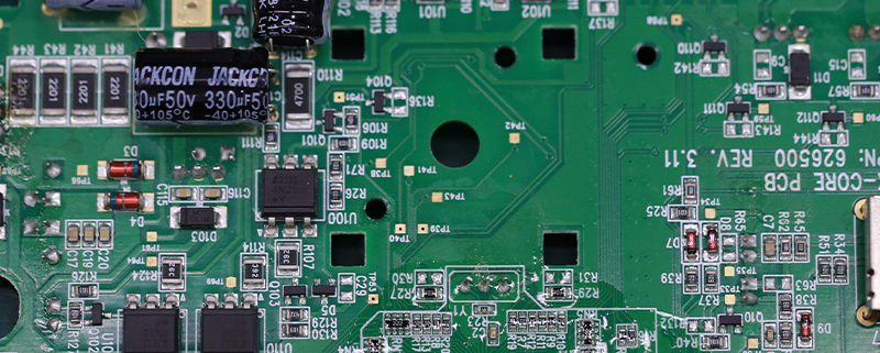
gh60 pcb
MTI is a high-tech company specializing in PCB manufacturing, PCB assembly and parts procurement services with more than 20 years of experience. We are committed to producing various types of printed circuit boards, mainly including single-sided, double-sided, multi-layer circuit boards, high-precision HDI, flexible boards (FPC), rigid-flex boards (including HDI), metal circuit boards and their SMD plugin.Product line application areas include:aerospace.Fast response, strict quality control, best service, and strong technical support export our PCB products to global markets,including,Dominica,Haiti,Lebanon,Papua New Guinea,Israel.
MTI would like to build long and stable business relationship with the customers from all over the world on the basis of mutual benefits and mutual progress;Choose MTI , Drive you Success!
| Product name | gh60 pcb |
| Keyword | 12 layer pcb thickness,printed circuit board assembly process |
| Place of Origin | China |
| Board Thickness | 1~3.2mm |
| Applicable Industries | aerospace, etc. |
| Service | OEM/ODM manufacturing |
| Certificate | ISO-9001:2015, ISO-14001:2015,ISO-13485:2012.UL/CSA |
| Solder Mask Color | Green |
| Advantage | We keep good quality and competitive price to ensure our customers benefit |
| Sales country | All over the world for example:Dominica,Haiti,Lebanon,Papua New Guinea,Israel |
We have rich experience engineer to create a layout using a software platform like Altium Designer. This layout shows you the exact appearance and placement of the components on your board.
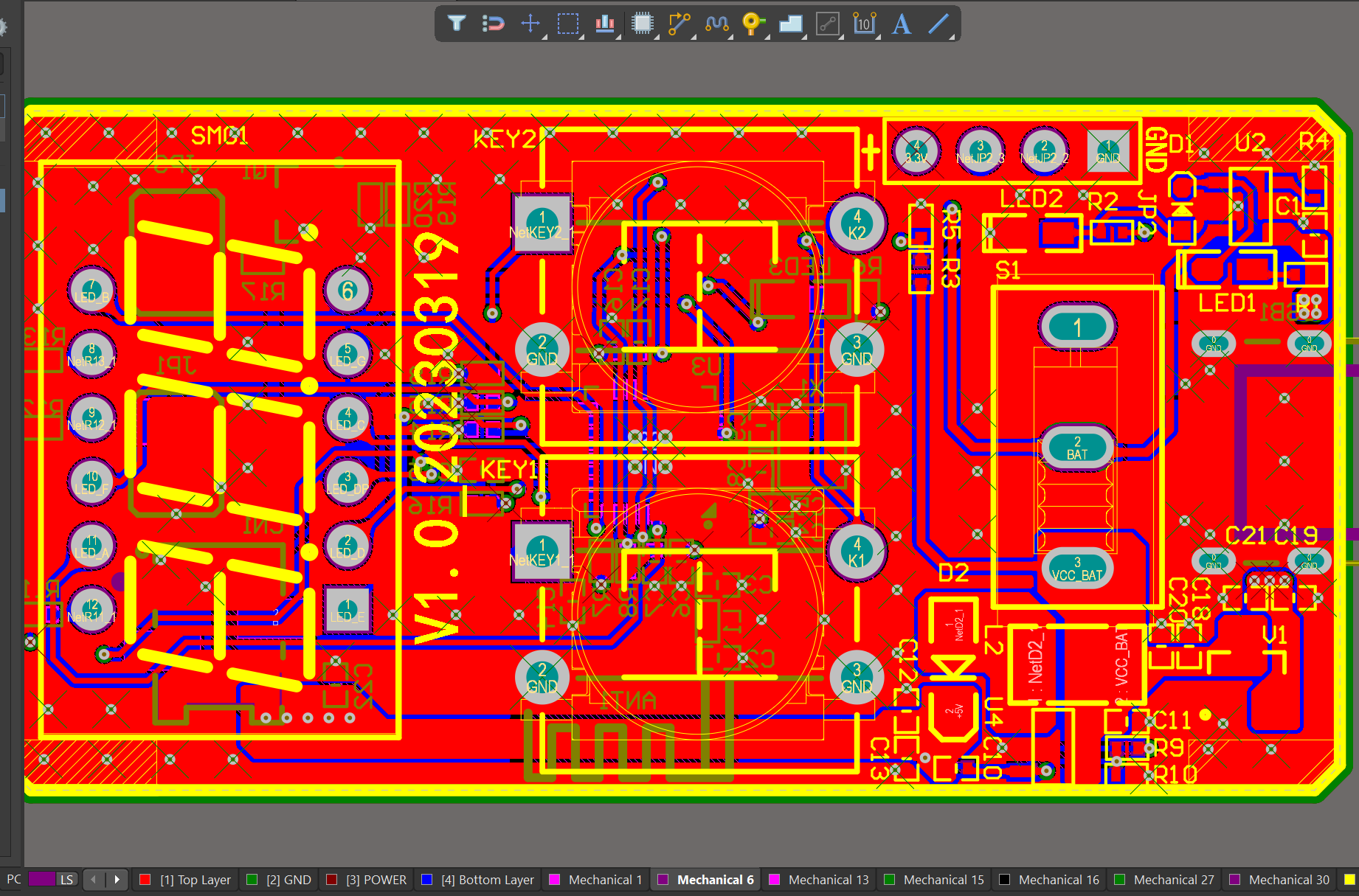
One of our Hardware Design Services is small-batch manufacturing, which allows you to test your idea quickly and verify the functionality of the hardware design and PCB board.

Your deliverables are always ahead of schedule and of the highest quality.
FAQs Guide
2.What are the differences between a prototype and production PCB?
3.What materials are commonly used to make PCBs?
4.What is the difference between single-sided and double-sided PCBs?
5.How does the number of layers in a PCB affect its functionality?
1.What is testability in PCB design and how is it achieved?
Our gh60 pcb products undergo strict quality control to ensure customer satisfaction.
Testability in PCB design refers to the ease and accuracy with which a printed circuit board (PCB) can be tested for functionality and performance. It is an important aspect of PCB design as it ensures that any defects or issues with the board can be identified and addressed before it is put into use.
Achieving testability in PCB design involves implementing certain design features and techniques that make it easier to test the board. These include:
1. Design for Test (DFT): This involves designing the PCB with specific test points and access points that allow for easy and accurate testing of different components and circuits.
2. Test Points: These are designated points on the PCB where test probes can be connected to measure voltage, current, and other parameters. Test points should be strategically placed to provide access to critical components and circuits.
3. Test Pads: These are small copper pads on the PCB that are used for attaching test probes. They should be placed close to the corresponding component or circuit for accurate testing.
4. Test Jigs: These are specialized tools used for testing PCBs. They can be custom-made for a specific PCB design and can greatly improve the accuracy and efficiency of testing.
5. Design for Manufacturability (DFM): This involves designing the PCB with manufacturing and testing in mind. This includes using standard components, avoiding complex layouts, and minimizing the number of layers to make testing easier.
6. Design for Debug (DFD): This involves designing the PCB with features that make it easier to identify and troubleshoot any issues that may arise during testing.
Overall, achieving testability in PCB design requires careful planning and consideration of the testing process. By implementing DFT, using test points and pads, and designing for manufacturability and debug, designers can ensure that their PCBs are easily testable and can be quickly and accurately diagnosed for any potential issues.
2.What are the differences between a prototype and production PCB?
We have a good reputation and image in the industry. The quality and price advantage of gh60 pcb products is an important factor in our hard overseas market.
1. Purpose: The main difference between a prototype and production PCB is their purpose. A prototype PCB is used for testing and validation of a design, while a production PCB is used for mass production and commercial use.
2. Design: Prototype PCBs are usually hand-soldered and have a simpler design compared to production PCBs. Production PCBs are designed with more precision and complexity to meet the specific requirements of the final product.
3. Materials: Prototype PCBs are often made with cheaper materials such as FR-4, while production PCBs use higher quality materials such as ceramic or metal core for better performance and durability.
4. Quantity: Prototype PCBs are usually made in small quantities, while production PCBs are manufactured in large quantities to meet the demand of the market.
5. Cost: Due to the use of cheaper materials and smaller quantities, prototype PCBs are less expensive compared to production PCBs. Production PCBs require a larger investment due to the use of higher quality materials and larger quantities.
6. Lead time: Prototype PCBs have a shorter lead time as they are made in smaller quantities and can be hand-soldered. Production PCBs have a longer lead time as they require more complex manufacturing processes and larger quantities.
7. Testing: Prototype PCBs are extensively tested to ensure the design is functional and meets the required specifications. Production PCBs also undergo testing, but the focus is more on quality control and consistency in mass production.
8. Documentation: Prototype PCBs may not have detailed documentation as they are often hand-soldered and used for testing purposes. Production PCBs have detailed documentation to ensure consistency in manufacturing and for future reference.
9. Modifications: Prototype PCBs are easier to modify and make changes to, as they are not mass-produced. Production PCBs are more difficult to modify as any changes can affect the entire production process.
10. Reliability: Production PCBs are designed and manufactured to be more reliable and durable, as they will be used in the final product. Prototype PCBs may not have the same level of reliability as they are used for testing and may not undergo the same level of quality control.
3.What materials are commonly used to make PCBs?
We have advantages in marketing and channel expansion. Suppliers have established good cooperative relations, continuously improved workflows, improved efficiency and productivity, and provided customers with high -quality products and services.
1. Copper: Copper is the most commonly used material for PCBs. It is used as the conductive layer for the circuit traces and pads.
2. FR4: FR4 is a type of fiberglass-reinforced epoxy laminate that is used as the base material for most PCBs. It provides good mechanical strength and insulation properties.
3. Solder mask: Solder mask is a layer of polymer that is applied over the copper traces to protect them from oxidation and to prevent solder bridges during assembly.
4. Silkscreen: Silkscreen is a layer of ink that is printed on top of the solder mask to provide component labels, reference designators, and other information.
5. Tin/lead or lead-free solder: Solder is used to attach components to the PCB and to create electrical connections between them.
6. Gold: Gold is used for plating the contact pads and vias on the PCB, as it provides good conductivity and corrosion resistance.
7. Silver: Silver is sometimes used as an alternative to gold for plating contact pads and vias, as it is cheaper but still provides good conductivity.
8. Nickel: Nickel is used as a barrier layer between the copper and gold or silver plating to prevent them from diffusing into each other.
9. Epoxy resin: Epoxy resin is used as an adhesive to bond the layers of the PCB together.
10. Ceramic: Ceramic materials are used for specialized PCBs that require high thermal conductivity and insulation properties, such as in high-power applications.
4.What is the difference between single-sided and double-sided PCBs?
Our mission is to provide customers with the best solutions for gh60 pcb.
Single-sided PCBs have copper traces and components on only one side of the board, while double-sided PCBs have copper traces and components on both sides of the board. This allows for more complex circuit designs and a higher density of components on a double-sided PCB. Single-sided PCBs are typically used for simpler circuits and are less expensive to manufacture, while double-sided PCBs are used for more complex circuits and are more expensive to manufacture.
5.How does the number of layers in a PCB affect its functionality?
We should have a stable supply chain and logistics capabilities, and provide customers with high -quality, low -priced gh60 pcb products.
The number of layers in a PCB (Printed Circuit Board) can affect its functionality in several ways:
1. Complexity: The number of layers in a PCB determines the complexity of the circuit design that can be implemented. More layers allow for more components and connections to be included in the design, making it more complex and versatile.
2. Size: A PCB with more layers can be smaller in size compared to a PCB with fewer layers, as it allows for a more compact layout of components and connections. This is especially important in devices with limited space, such as smartphones and wearables.
3. Signal Integrity: The number of layers in a PCB can also affect the signal integrity of the circuit. More layers allow for better routing of signals, reducing the chances of interference and crosstalk between different components.
4. Power Distribution: PCBs with more layers can have dedicated power and ground planes, which help in distributing power evenly across the circuit. This improves the overall performance and stability of the circuit.
5. Cost: The number of layers in a PCB can also affect its cost. More layers mean more materials and manufacturing processes, which can increase the overall cost of the PCB.
6. Thermal Management: PCBs with more layers can have better thermal management, as they allow for the placement of thermal vias and heat sinks to dissipate heat more efficiently. This is important for high-power applications that generate a lot of heat.
In summary, the number of layers in a PCB can significantly impact its functionality, complexity, size, signal integrity, power distribution, cost, and thermal management. Designers must carefully consider the number of layers required for a PCB based on the specific requirements of the circuit and the device it will be used in.
Tags:100 mechanical keyboard pcb,12 layer pcb stack up
