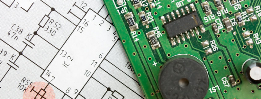
h60 pcb
MTI is a professional manufacturer of PCB and PCBA , we supply one-stop service. The company’s main services include PCB production, PCB Assembly and electronic materials purchasing, SMT patch, circuit board welding, circuit board plug-in.
Our clientele spans across major continents (Africa,Europe,America)and encompasses various industries, including healthcare,military
| Product name | h60 pcb |
| Keyword | 10 pin pcb connector,printed circuit board assemblies,007 pcb,eft pcb |
| Place of Origin | China |
| Board Thickness | 1~3.2mm |
| Applicable Industries | military, etc. |
| Service | OEM/ODM manufacturing |
| Certificate | ISO-9001:2015, ISO-14001:2015,ISO-13485:2012.UL/CSA |
| Solder Mask Color | White |
| Advantage | We keep good quality and competitive price to ensure our customers benefit |
| Sales country | All over the world for example:Romania,Congo, Republic of the,Panama,Yemen,Sri Lanka,Jersey,Mali |
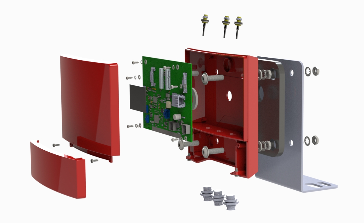
One of our Hardware Design Services is small-batch manufacturing, which allows you to test your idea quickly and verify the functionality of the hardware design and PCB board.

Your deliverables are always ahead of schedule and of the highest quality.
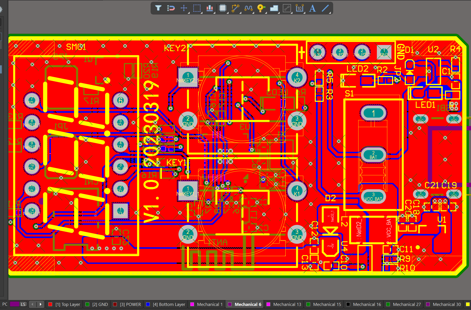
We have rich experience engineer to create a layout using a software platform like Altium Designer. This layout shows you the exact appearance and placement of the components on your board.
FAQs Guide
2.Can a PCB have different levels of flexibility?
3.What is the minimum distance required between components on a PCB?
4.Can PCBs be made with different thicknesses?
5.Can PCBs have different shapes and sizes?
6.Can PCBs be designed with high-speed and high-frequency applications in mind?
7.How does the type of vias used affect the performance of a PCB?
8.How do PCBs support the integration of different electronic components?
1.What are the factors to consider when choosing the right PCB material for a specific application?
We are centered on customers and always pay attention to customers’ needs for h60 pcb products.
1. Electrical properties: The electrical properties of the PCB material, such as dielectric constant, loss tangent, and insulation resistance, should be carefully considered to ensure optimal performance for the specific application.
2. Thermal properties: The thermal conductivity and coefficient of thermal expansion of the PCB material are important factors to consider, especially for applications that require high power or operate in extreme temperatures.
3. Mechanical properties: The mechanical strength, stiffness, and flexibility of the PCB material should be evaluated to ensure it can withstand the physical stresses and strains of the application.
4. Chemical resistance: The PCB material should be resistant to any chemicals or solvents that it may come into contact with during its use.
5. Cost: The cost of the PCB material should be considered, as it can vary significantly depending on the type and quality of the material.
6. Availability: Some PCB materials may be more readily available than others, which can affect production timelines and costs.
7. Manufacturing process: The chosen PCB material should be compatible with the manufacturing process, such as etching, drilling, and plating, to ensure efficient and reliable production.
8. Environmental factors: The application environment, such as humidity, moisture, and exposure to UV light, should be taken into account when selecting a PCB material to ensure it can withstand these conditions.
9. Signal integrity: For high-frequency applications, the PCB material should have low signal loss and good signal integrity to prevent interference and ensure accurate signal transmission.
10. RoHS compliance: If the application requires compliance with environmental regulations, such as the Restriction of Hazardous Substances (RoHS) directive, the PCB material should be chosen accordingly.
2.Can a PCB have different levels of flexibility?
We have a wide range of h60 pcb customer groups and establishes long -term cooperative relationships with partners.
Yes, a PCB (printed circuit board) can have different levels of flexibility depending on its design and materials used. Some PCBs are rigid and cannot bend or flex at all, while others are designed to be flexible and can bend or twist to a certain degree. There are also PCBs that have a combination of rigid and flexible areas, known as flex-rigid PCBs. The level of flexibility in a PCB is determined by factors such as the type of substrate material, the thickness and number of layers, and the type of circuit design.
3.What is the minimum distance required between components on a PCB?
We have advanced production equipment and technology to meet the needs of customers, and can provide customers with high quality, low priced h60 pcb products.
The minimum distance required between components on a PCB depends on various factors such as the type of components, their size, and the manufacturing process used. Generally, the minimum distance between components is determined by the manufacturer’s design rules and guidelines.
For surface mount components, the minimum distance between components is typically 0.2mm to 0.3mm. This distance is necessary to ensure that the solder paste does not bridge between the pads during the reflow process.
For through-hole components, the minimum distance between components is typically 1mm to 2mm. This distance is necessary to ensure that the components do not interfere with each other during the assembly process.
In high-speed and high-frequency applications, the minimum distance between components may need to be increased to avoid signal interference and crosstalk. In these cases, the manufacturer’s design rules and guidelines should be followed closely.
Overall, the minimum distance between components on a PCB should be determined based on the specific requirements of the design and the capabilities of the manufacturing process.
4.Can PCBs be made with different thicknesses?
We operate our h60 pcb business with integrity and honesty.
Yes, PCBs (printed circuit boards) can be made with different thicknesses. The thickness of a PCB is determined by the thickness of the copper layer and the thickness of the substrate material. The copper layer thickness can range from 0.5 oz to 3 oz, while the substrate material thickness can range from 0.2 mm to 3.2 mm. The most common thicknesses for PCBs are 1.6 mm and 0.8 mm, but custom thicknesses can be requested from PCB manufacturers. The thickness of a PCB can affect its mechanical strength, thermal properties, and electrical performance.
5.Can PCBs have different shapes and sizes?
Our company has many years of h60 pcb experience and expertise.
Yes, PCBs (printed circuit boards) can have different shapes and sizes depending on the specific design and purpose of the circuit. They can range from small and compact to large and complex, and can be rectangular, circular, or even irregularly shaped. The shape and size of a PCB is determined by the layout of the components and the desired functionality of the circuit.
6.Can PCBs be designed with high-speed and high-frequency applications in mind?
We attach importance to the innovation ability and team spirit of employees, have advanced R & D facilities and laboratories, and have a good quality management system.
Yes, PCBs can be designed with high-speed and high-frequency applications in mind. This involves careful consideration of the layout, trace routing, and component placement to minimize signal loss and interference. Specialized materials and techniques, such as controlled impedance routing and differential pairs, can also be used to improve signal integrity and reduce noise. Additionally, the use of advanced simulation and analysis tools can help optimize the design for high-speed and high-frequency performance.
7.How does the type of vias used affect the performance of a PCB?
Being one of the top h60 pcb manufacturers in China, We attach great importance to this detail.
The type of vias used can affect the performance of a PCB in several ways:
1. Signal Integrity: Vias can act as discontinuities in the signal path, causing reflections and signal degradation. The type of via used can impact the impedance and signal integrity of the PCB. For high-speed signals, it is important to use controlled impedance vias to maintain signal integrity.
2. Electrical Performance: The type of via used can also affect the electrical performance of the PCB. For example, through-hole vias have lower resistance and inductance compared to blind or buried vias, which can affect the power delivery and signal transmission on the PCB.
3. Thermal Performance: Vias can also play a role in the thermal performance of a PCB. Through-hole vias can act as thermal vias, allowing heat to dissipate from one layer to another. Blind and buried vias, on the other hand, can trap heat and affect the overall thermal management of the PCB.
4. Manufacturing Cost: The type of via used can also impact the cost of manufacturing the PCB. Blind and buried vias require more complex and expensive processes, while through-hole vias are relatively simpler and cheaper to manufacture.
5. PCB Size and Density: The type of via used can also affect the size and density of the PCB. Blind and buried vias take up less space on the surface of the PCB, allowing for higher density designs. This can be beneficial for smaller and more compact PCBs.
Overall, the type of vias used can have a significant impact on the performance, cost, and design of a PCB. It is important to carefully consider the type of vias needed for a specific application to ensure optimal performance and functionality of the PCB.
8.How do PCBs support the integration of different electronic components?
We actively participate in the h60 pcb industry associations and organization activities. The corporate social responsibility performed well, and the focus of brand building and promotion.
PCBs (Printed Circuit Boards) are essential for the integration of different electronic components in electronic devices. They provide a platform for connecting and supporting the various components, allowing them to work together seamlessly. Here are some ways in which PCBs support the integration of different electronic components:
1. Electrical connections: PCBs have a network of copper traces that connect the different electronic components on the board. These traces act as conductors, allowing electricity to flow between the components and enabling them to communicate and work together.
2. Mounting surface: PCBs provide a stable and secure mounting surface for electronic components. The components are soldered onto the board, ensuring that they are firmly attached and will not move or become loose during operation.
3. Space-saving: PCBs are designed to be compact and space-saving, allowing for the integration of multiple components on a single board. This is especially useful in small electronic devices where space is limited.
4. Customization: PCBs can be customized to accommodate different types and sizes of electronic components. This allows for flexibility in design and the integration of a wide range of components, making it easier to create complex electronic devices.
5. Signal routing: PCBs have multiple layers, with each layer dedicated to a specific function. This allows for efficient routing of signals between components, reducing interference and ensuring that the components can communicate effectively.
6. Power distribution: PCBs have dedicated power planes that distribute power to the different components on the board. This ensures that each component receives the required amount of power, preventing damage and ensuring proper functioning.
7. Thermal management: PCBs also play a crucial role in managing the heat generated by electronic components. They have copper layers that act as heat sinks, dissipating heat and preventing the components from overheating.
In summary, PCBs provide a robust and efficient platform for integrating different electronic components. They enable the components to work together seamlessly, ensuring the proper functioning of electronic devices.
Tags:printed circuit assembly,pcb circuit board,flex pcba manufacturer,12 layer pcb
