Understanding the specific demands concerning varistors in Montagem de PCB (PCBA) design is essential. Here’s a breakdown of what PCBA design demands from varistors:

Operating Temperature/Storage:

Maintain the working temperature of the circuit within the specified range outlined in the product’s specifications. After montagem, store the circuit within the product’s specified temperature range when it’s not operational. Avoid using temperatures higher than the specified maximum operating temperature.

Operating Voltage:

Keep the voltage applied across the varistor terminals below the maximum permissible voltage. Incorrect usage might result in product failure, short circuits, or potential heating issues. Although the usage voltage should be below the rated voltage, in cases of continuous high-frequency or pulse voltage, thoroughly assess the varistor’s reliability.

Component Heating:

Ensure that the surface temperature of the varistor remains below the highest specified operating temperature (considering temperature elevation caused by the component’s self-heating) as dictated in the product specifications. Confirm varistor temperature elevation due to circuit conditions under the actual operational state of the equipment.

Restricted Usage Areas:

  • Varistors shouldn’t be used in the following environments:
  • Places with water or saltwater.
  • Areas prone to condensation.
  • Locations with corrosive gases (such as hydrogen sulfide, sulfur dioxide, ammonia, etc.).
  • Conditions where the vibration or shock exceeds the specified range in the product specifications.
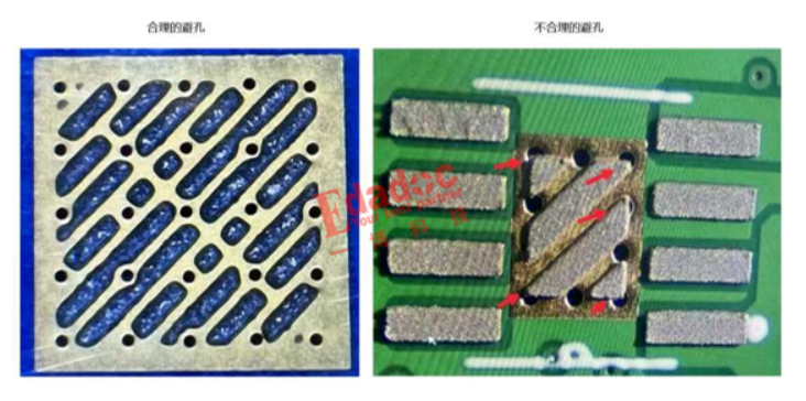
PCB Selection:

The performance of aluminum oxide circuit boards may deteriorate due to thermal shock (temperature cycling). It’s crucial to confirm if the circuit board affects the product quality during use.
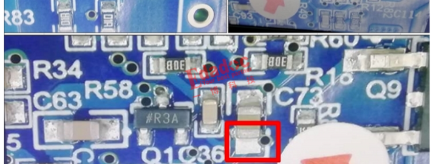
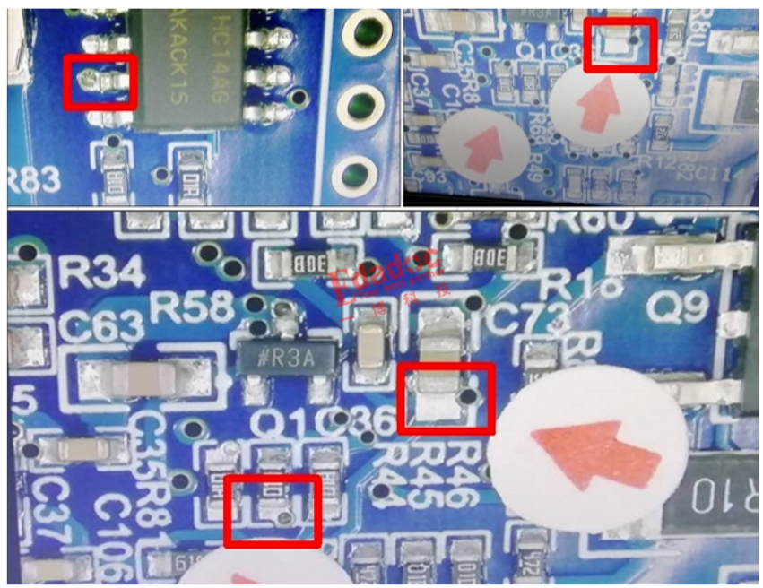
Pad Size Setting:

More soldering leads to increased pressure on the varistor, leading to quality issues like surface cracks. Therefore, when designing the solder pad on the circuit board, suitable shapes and sizes must be set according to the soldering volume. Maintain an equal size for the solder pads. Uneven solder volumes on the left and right pads can cause delayed solidification on the side with more solder, leading to stress-induced cracks on the other side during solder cooling.

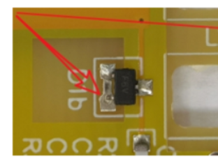
Component Configuration:

Installing varistors in PCBA or subjecting circuit boards to bending during operation may result in varistor fractures. Hence, configuring components must consider the circuit board’s resistance to bending and avoid applying excessive pressure.

No processo de produção diário, a atenção meticulosa a vários pormenores de produção é crucial para garantir uma qualidade de fabrico superior. Cumprir rigorosamente os requisitos estipulados com uma abordagem dedicada e responsável durante a produção é fundamental para um processamento optimizado, que é essencial para a manutenção do crescimento da empresa. Abaixo, a nossa equipa da fábrica de montagem SMT em MTI PCBA compilou um guia para as principais considerações durante os processos de montagem SMT. Vamos aprofundá-lo em conjunto:

Temperatura e humidade da oficina

Manter as condições ideais na oficina de produção é essencial. Para as oficinas SMT, a temperatura ideal é de 24±2℃, com níveis de humidade à volta de 40±10%RH. Temperaturas extremas podem levar a problemas de solda, como contas de estanho ou bolhas de solda e problemas relacionados ao estêncil durante a impressão.

Armazenamento de materiais

Na montagem pré-SMT, as condições de armazenamento dos materiais são frequentemente ignoradas. Por exemplo, as placas de circuito impresso expostas ao ar durante longos períodos tendem a absorver humidade, o que resulta numa soldadura deficiente mais tarde. Além disso, é necessária uma atenção especial para o armazenamento de chips BGA e IC, que requerem um ambiente seco para evitar a oxidação.

Pasta de solda

A pasta de solda, um material essencial na montagem SMT, é composta principalmente por pó de estanho e fluxo. Uma vez que o fluxo desempenha um papel significativo em todo o processo de soldadura, é crucial selecionar uma pasta de solda de alta qualidade. Os procedimentos de pré-utilização, como o refluxo e a agitação da pasta de solda, são pormenores essenciais a não descurar.

Processo de soldadura

O processo de soldadura por refluxo ocupa uma posição crítica na montagem SMT, tendo um impacto direto na qualidade da soldadura. A qualidade da soldadura de montagem em superfície é um dos factores mais críticos. As considerações sobre a soldadura por refluxo envolvem normalmente a temperatura do forno, o pré-aquecimento e as temperaturas óptimas.

Controlo de qualidade pós-refluxo (QC)

A qualidade do produto representa a reputação da fábrica, e a qualidade da soldadura influencia-a significativamente. Produtos excepcionais são essenciais para manter uma vantagem competitiva no mercado. PCBA indústria. Assim, é imperativo um controlo rigoroso da qualidade do processo de soldadura, concentrando-se nos pormenores para evitar defeitos como juntas de soldadura abertas, saltos de soldadura ou pontes.

Para mais informações sobre prototipagem rápida na montagem SMT, high-end PCBA fabrico, SMT preços de montagem e muito mais, sinta-se à vontade para explorar MTI PCBA  para obter informações pormenorizadas.

When it comes to Surface Mount Technology (SMT) production, cases of welding failure caused by missing drill files are not uncommon.

Solder paste printing in SMT welding is a crucial and rather complex process, with data suggesting that 60-70% of defects in SMT production stem from solder paste printing.

Interestingly, these defects are not equipment-related but primarily emerge during engineering assessments and stencil optimizations. In particular, the absence of drilling files during engineering can lead to various SMT welding defects.

According to data provided by Company E’s Engineering Department at major welding factories, about 15% of SMT welding cases lack drilling layer files. This omission leads to at least one or more daily orders where customers fail to provide these essential files. It incurs significant communication costs, estimated at around 100 minutes per day and over 43 hours per month, arising from email exchanges between engineers, PMC, and customers to confirm and fulfill these requirements.

The stencil plays a pivotal role in SMT welding and requires a systematic approach beyond simple hole drilling. Understanding how to prevent tin ingress causing soldering issues, the necessity of drilling layer files for stencil design, and addressing various real-world cases are crucial.

  1. For instance, issues arise when edge holes on solder pads aren’t identified due to the absence of drilling files. The consequence: unsatisfactory soldering, false soldering, and inadequate tin in resistors or connectors.

2. Similarly, the lack of avoidance holes in QFN ground solder pads results in tin ingress and false soldering. Here, it’s vital to avoid or increase tin filling in the holes to ensure sufficient coverage. Failure to provide drilling layer files prevents timely detection and avoidance of such problems during stencil creation.

Furthermore, the rush to create stencils without physical inspection of the PCB bare board can lead to issues. When customers fail to provide drilling layer files, issues such as unanticipated plate-through holes can arise during stencil creation, leading to welding anomalies.

To mitigate these concerns, it’s essential to evaluate plate-through holes for chips, maintain a distance between through-holes and SMDs, and understand the importance of resin plug-hole electroplating processes in PCB design.

In summary, by avoiding plate-through holes and ensuring the provision of drilling layer files for stencil design, welding quality can be significantly improved. This not only aids in precise hole identification but also prevents unnecessary or insufficient holes, thereby averting potential quality hazards due to poor design choices.