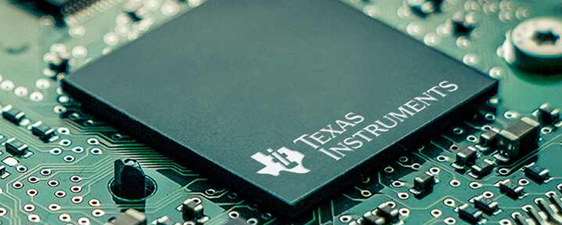
10 pcb
MTI is a manufacturer of high-precision printed circuit board (PCB).We specialize in the manufacture of high precision double-sided and multilayer printed circuit boards, We provide high quality products and faster service for high-tech companies.
We have a group of experienced staff and high-quality management team, set up a complete quality assurance system. Products include FR-4 PCB, Metal PCB and RFPCB (ceramic PCB, PTFE PCB), 10 pcb,etc. Have rich experience in the production of thick copper PCB, RF PCB, high Tg PCB, HDI PCB.With ISO9001, ISO14001, TS16949, ISO 13485, RoHS certifications.
| Product name | 10 pcb |
| Keyword | 108 key pcb,pcb fab,China circuit board assembly,1.2mm pcb,pcb assembly and manufacturing |
| Place of Origin | China |
| Board Thickness | 1~3.2mm |
| Applicable Industries | automotive electronics , etc. |
| Service | OEM/ODM manufacturing |
| Certificate | ISO-9001:2015, ISO-14001:2015,ISO-13485:2012.UL/CSA |
| Solder Mask Color | Blue |
| Advantage | We keep good quality and competitive price to ensure our customers benefit |
| Sales country | All over the world for example:Albania,Algeria,Morocco,Bangladesh,Poland,Europa Island,Croatia,Glorioso Islands |
Your deliverables are always ahead of schedule and of the highest quality.
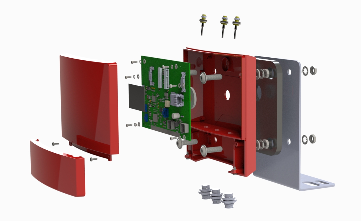
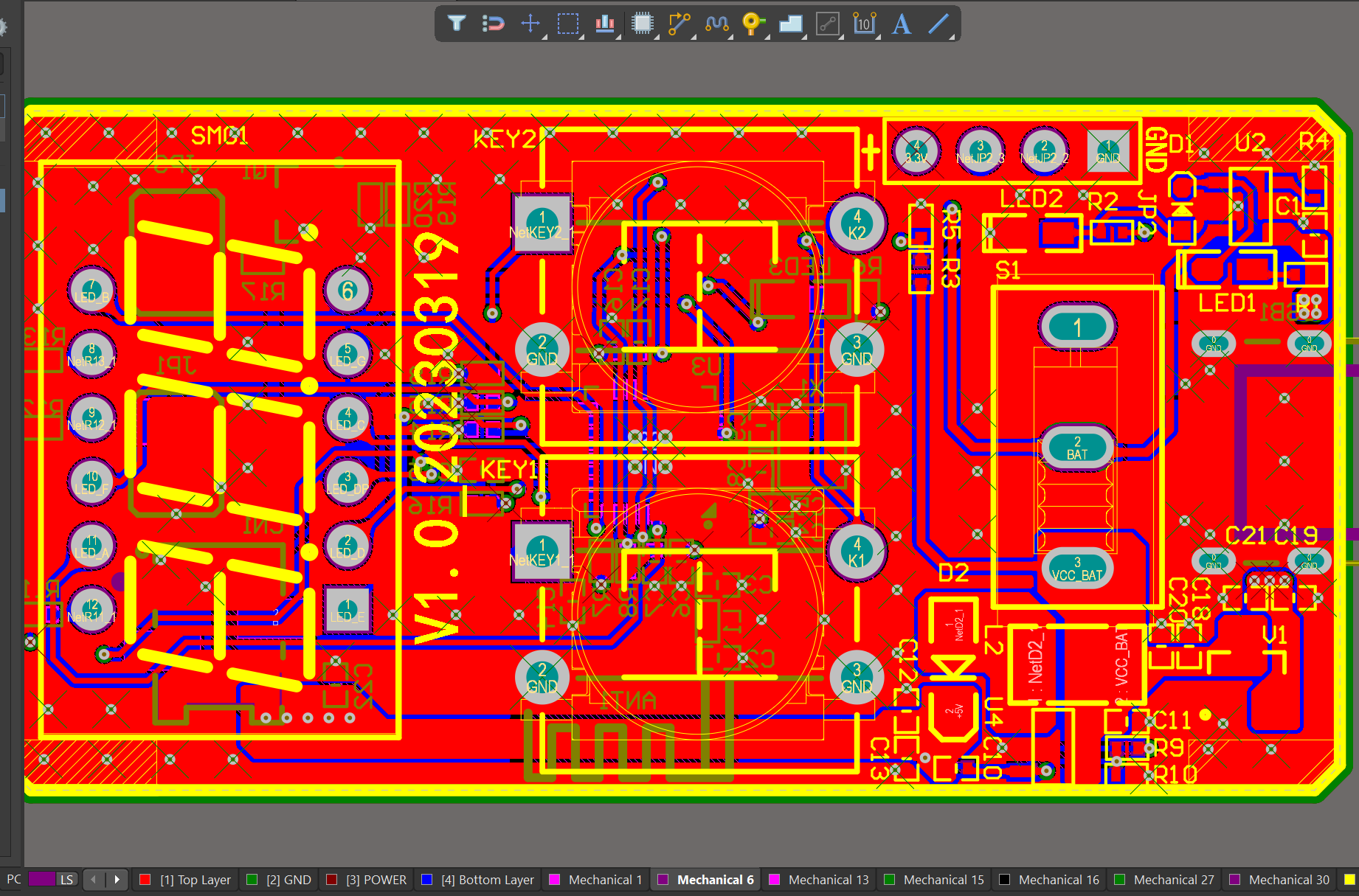
We have rich experience engineer to create a layout using a software platform like Altium Designer. This layout shows you the exact appearance and placement of the components on your board.
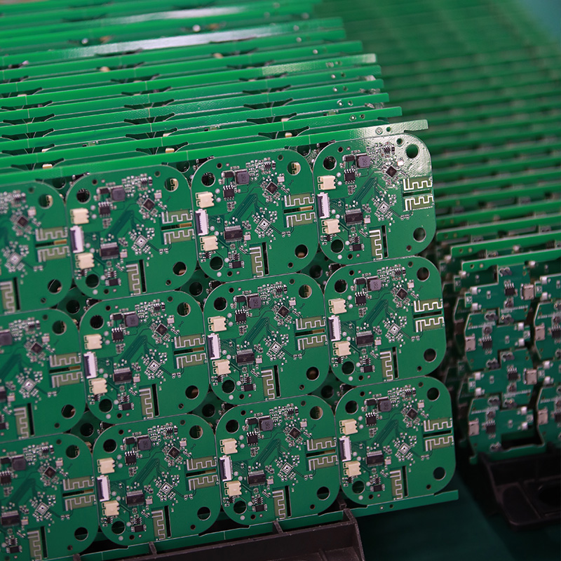
One of our Hardware Design Services is small-batch manufacturing, which allows you to test your idea quickly and verify the functionality of the hardware design and PCB board.

FAQs Guide
2.Can PCBs be designed with high-speed and high-frequency applications in mind?
3.How do PCBs support the integration of different electronic components?
4.Can PCBs have multiple power planes?
5.How do surface mount components differ from through-hole components in a PCB?
1.What are the key features of a PCB?
We are committed to providing personalized solutions and established long -term strategic cooperative relationships with customers.
1. Substrate: The base material on which the circuit is printed, usually made of fiberglass or composite epoxy.
2. Conductive Traces: Thin copper lines that connect the components on the PCB.
3. Pads: Small copper areas on the PCB surface where components are soldered.
4. Vias: Holes drilled through the PCB to connect the different layers of the circuit.
5. Solder Mask: A layer of protective material that covers the copper traces and pads, preventing accidental short circuits.
6. Silkscreen: A layer of ink that is printed on the PCB to label the components and provide other useful information.
7. Components: Electronic devices such as resistors, capacitors, and integrated circuits that are mounted on the PCB.
8. Mounting Holes: Holes drilled on the PCB to allow it to be securely attached to a larger device or enclosure.
9. Copper Pour: Large areas of copper that are used to provide a common ground or power plane for the circuit.
10. Edge Connectors: Metal contacts on the edge of the PCB that allow it to be connected to other circuits or devices.
11. Solder Bridges: Small areas of exposed copper that allow for the connection of two or more traces.
12. Test Points: Small pads or holes on the PCB that allow for testing and troubleshooting of the circuit.
13. Silkscreen Legend: Printed text or symbols on the silkscreen layer that provide additional information about the PCB and its components.
14. Designators: Letters or numbers printed on the silkscreen layer to identify specific components on the PCB.
15. Reference Designators: A combination of letters and numbers that identify the location of a component on the PCB according to the schematic diagram.
2.Can PCBs be designed with high-speed and high-frequency applications in mind?
We attach importance to the innovation ability and team spirit of employees, have advanced R & D facilities and laboratories, and have a good quality management system.
Yes, PCBs can be designed with high-speed and high-frequency applications in mind. This involves careful consideration of the layout, trace routing, and component placement to minimize signal loss and interference. Specialized materials and techniques, such as controlled impedance routing and differential pairs, can also be used to improve signal integrity and reduce noise. Additionally, the use of advanced simulation and analysis tools can help optimize the design for high-speed and high-frequency performance.
3.How do PCBs support the integration of different electronic components?
We actively participate in the 10 pcb industry associations and organization activities. The corporate social responsibility performed well, and the focus of brand building and promotion.
PCBs (Printed Circuit Boards) are essential for the integration of different electronic components in electronic devices. They provide a platform for connecting and supporting the various components, allowing them to work together seamlessly. Here are some ways in which PCBs support the integration of different electronic components:
1. Electrical connections: PCBs have a network of copper traces that connect the different electronic components on the board. These traces act as conductors, allowing electricity to flow between the components and enabling them to communicate and work together.
2. Mounting surface: PCBs provide a stable and secure mounting surface for electronic components. The components are soldered onto the board, ensuring that they are firmly attached and will not move or become loose during operation.
3. Space-saving: PCBs are designed to be compact and space-saving, allowing for the integration of multiple components on a single board. This is especially useful in small electronic devices where space is limited.
4. Customization: PCBs can be customized to accommodate different types and sizes of electronic components. This allows for flexibility in design and the integration of a wide range of components, making it easier to create complex electronic devices.
5. Signal routing: PCBs have multiple layers, with each layer dedicated to a specific function. This allows for efficient routing of signals between components, reducing interference and ensuring that the components can communicate effectively.
6. Power distribution: PCBs have dedicated power planes that distribute power to the different components on the board. This ensures that each component receives the required amount of power, preventing damage and ensuring proper functioning.
7. Thermal management: PCBs also play a crucial role in managing the heat generated by electronic components. They have copper layers that act as heat sinks, dissipating heat and preventing the components from overheating.
In summary, PCBs provide a robust and efficient platform for integrating different electronic components. They enable the components to work together seamlessly, ensuring the proper functioning of electronic devices.
4.Can PCBs have multiple power planes?
We maintain a stable growth through reasonable capital operations, focus on industry development trends and cutting -edge technologies, and focus on product quality and safety performance.
Yes, PCBs can have multiple power planes. Power planes are layers of copper on a PCB that are used to distribute power and ground signals throughout the board. Multiple power planes can be used to provide different voltages or to separate sensitive analog signals from noisy digital signals. They can also be used to increase the current carrying capacity of the board. The number and arrangement of power planes on a PCB will depend on the specific design requirements and can vary greatly.
5.How do surface mount components differ from through-hole components in a PCB?
We pay attention to user experience and product quality, and provide the best product quality and lowest production cost for cooperative customers.
Surface mount components (SMD) and through-hole components (THD) are two different types of electronic components used in printed circuit boards (PCBs). The main difference between them lies in their method of mounting onto the PCB.
1. Mounting Method:
The main difference between SMD and THD components is their mounting method. SMD components are mounted directly onto the surface of the PCB, while THD components are inserted into holes drilled into the PCB and soldered on the other side.
2. Size:
SMD components are generally smaller in size compared to THD components. This is because SMD components do not require leads or pins for mounting, allowing for a more compact design. THD components, on the other hand, have leads or pins that need to be inserted into the PCB, making them larger in size.
3. Space Efficiency:
Due to their smaller size, SMD components allow for a more space-efficient design on the PCB. This is especially important in modern electronic devices where space is limited. THD components take up more space on the PCB due to their larger size and the need for holes to be drilled.
4. Cost:
SMD components are generally more expensive than THD components. This is because SMD components require more advanced manufacturing techniques and equipment, making them costlier to produce.
5. Assembly Process:
The assembly process for SMD components is automated, using pick-and-place machines to accurately place the components onto the PCB. This makes the process faster and more efficient compared to THD components, which require manual insertion and soldering.
6. Electrical Performance:
SMD components have better electrical performance compared to THD components. This is because SMD components have shorter leads, resulting in less parasitic capacitance and inductance, leading to better signal integrity.
In summary, SMD components offer a more compact design, better electrical performance, and a faster assembly process, but at a higher cost. THD components, on the other hand, are larger in size, less expensive, and can handle higher power and voltage ratings. The choice between SMD and THD components depends on the specific requirements of the PCB design and the intended use of the electronic device.
Tags:pcb assembly and manufacturing,prototype printed circuit board assembly,pcb assembly and production process
