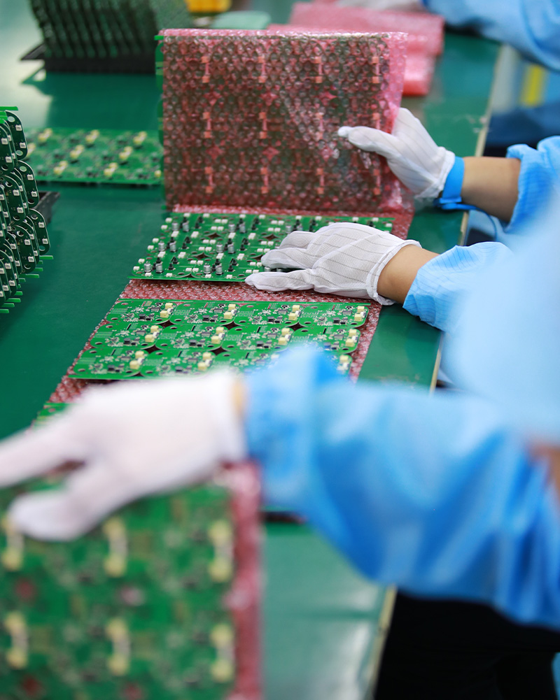
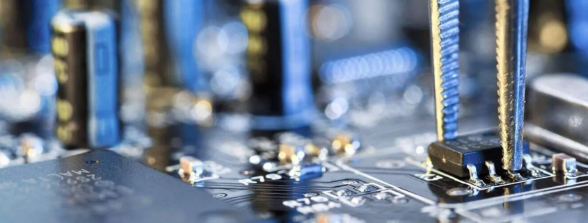
MTI specializes in turn-key electronics manufacturing manufacturing service, providing comprehensive solutions from product documentation to high-quality product delivery worldwide.

With a wide range, good quality, reasonable prices and stylish designs, our products are extensively used in telecommunications.Our products are widely recognized and trusted by users and can meet continuously changing economic and social needs.We welcome new and old customers from all walks of life to contact us for future business relationships and mutual success!

Product name pcb assembling
Keyword 3080 fe pcb,3018 pcb,1.2mm pcb,2.4 ghz pcb trace antenna
Place of Origin China
Board Thickness 2~3.2mm
Applicable Industries telecommunications, etc.
Service OEM/ODM manufacturing
Certificate ISO-9001:2015, ISO-14001:2015,ISO-13485:2012.UL/CSA
Solder Mask Color Black
Advantage We keep good quality and competitive price to ensure our customers benefit
Sales country All over the world for example:Solomon Islands,Costa Rica,Saint Pierre and Miquelon,Czech Republic,Benin,Comoros,Navassa Island,Luxembourg,Europa Island


One of our Hardware Design Services is small-batch manufacturing, which allows you to test your idea quickly and verify the functionality of the hardware design and PCB board.

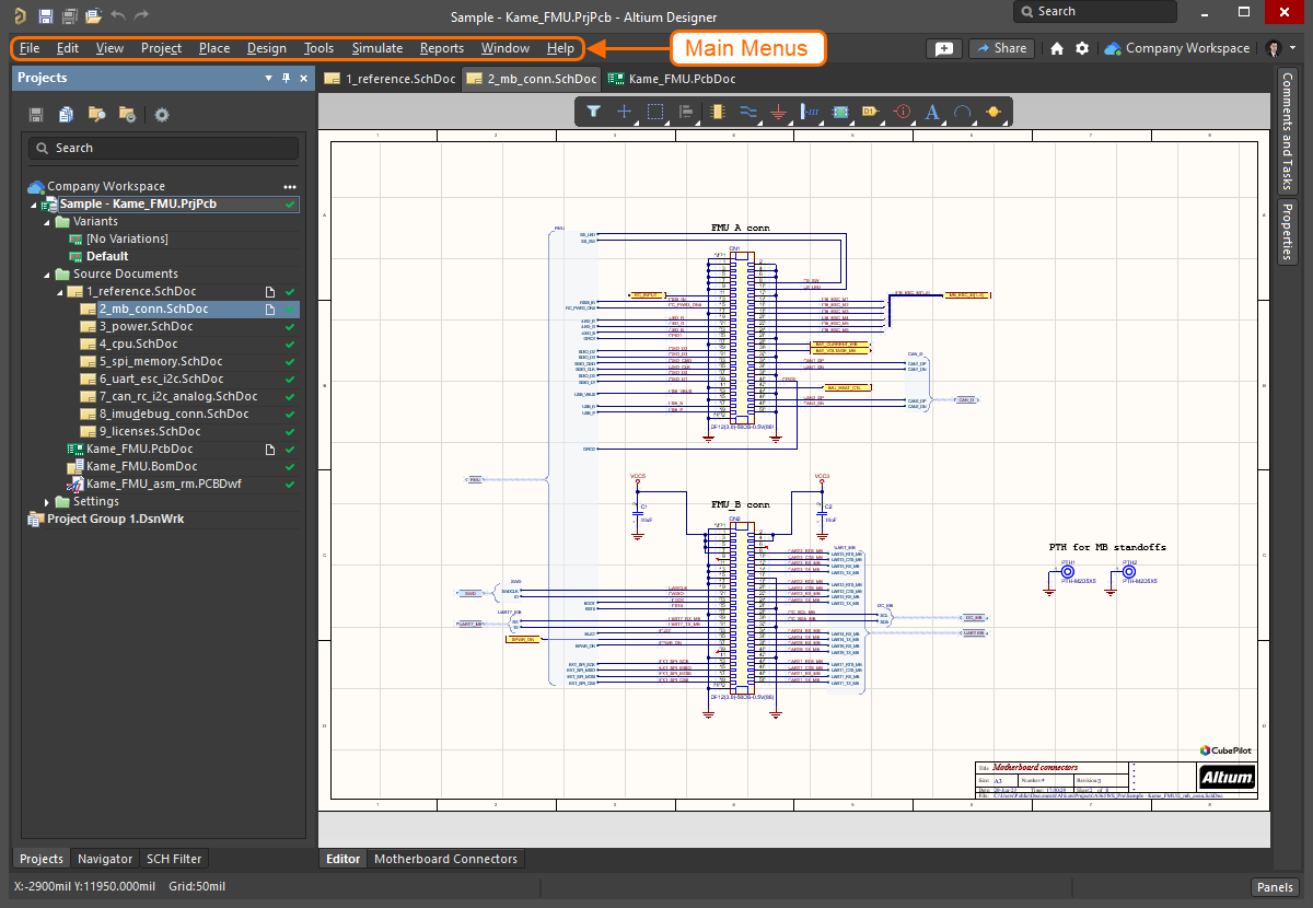
We have rich experience engineer to create a layout using a software platform like Altium Designer. This layout shows you the exact appearance and placement of the components on your board.
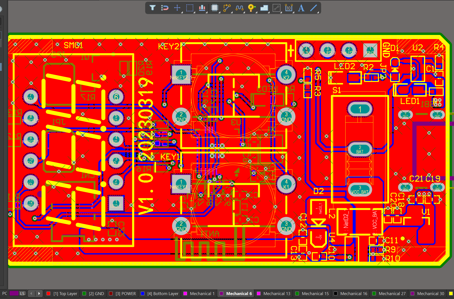
Your deliverables are always ahead of schedule and of the highest quality.
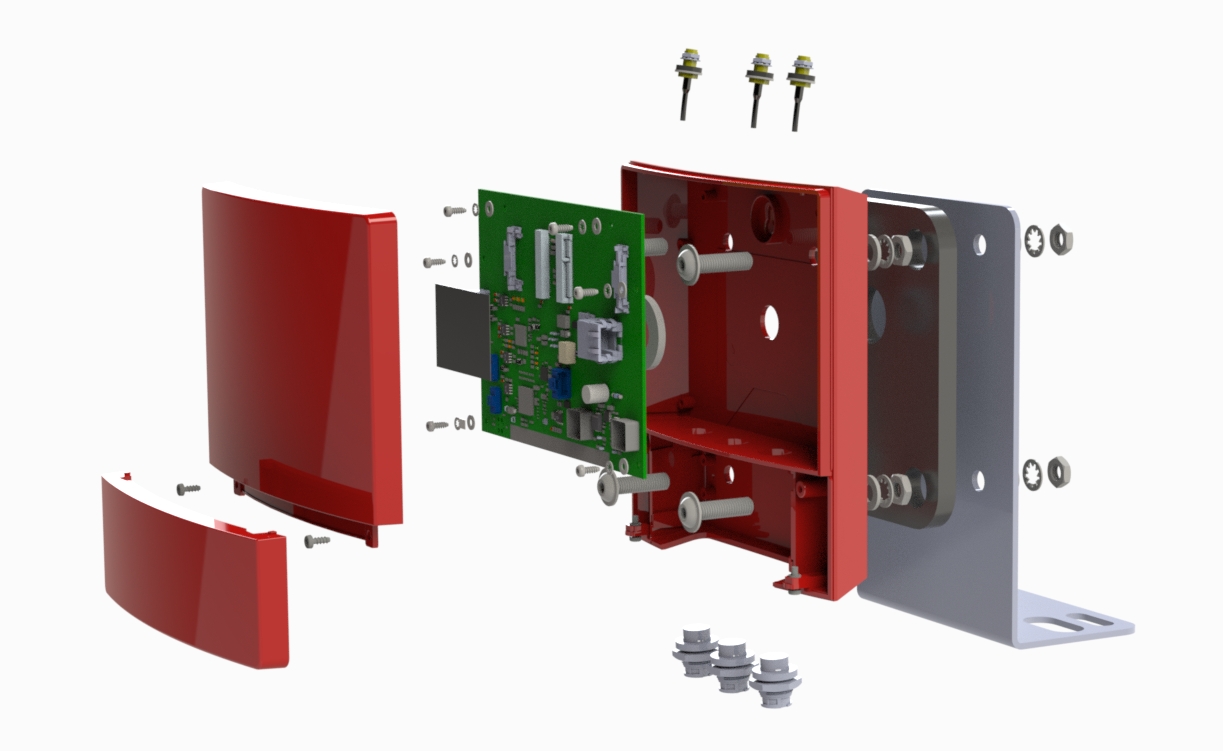
FAQs Guide

1.How does the type of solder mask used affect the PCB’s performance?

We have broad development space in domestic and foreign markets. pcb assemblings have great advantages in terms of price, quality, and delivery date.
The type of solder mask used can affect the PCB’s performance in several ways:

1. Insulation: Solder mask is used to insulate the copper traces on a PCB, preventing them from coming into contact with each other and causing a short circuit. The type of solder mask used can affect the level of insulation provided, which can impact the overall reliability and functionality of the PCB.

2. Solderability: Solder mask also plays a crucial role in the soldering process. The type of solder mask used can affect the surface tension and wetting properties of the solder, which can impact the quality of the solder joints and the overall reliability of the PCB.

3. Thermal resistance: Solder mask can also act as a thermal barrier, protecting the PCB from excessive heat. The type of solder mask used can affect the thermal resistance of the PCB, which can impact its ability to dissipate heat and its overall thermal performance.

4. Chemical resistance: Solder mask is also exposed to various chemicals during the PCB manufacturing process, such as flux and cleaning agents. The type of solder mask used can affect its resistance to these chemicals, which can impact the overall durability and reliability of the PCB.

5. Electrical properties: The type of solder mask used can also affect the electrical properties of the PCB, such as its dielectric constant and dissipation factor. These properties can impact the performance of high-frequency circuits and signal integrity.

Overall, the type of solder mask used can have a significant impact on the performance, reliability, and durability of a PCB. It is essential to carefully select the appropriate solder mask for a specific application to ensure optimal performance.

2.What is the minimum distance required between components on a PCB?

We have advanced production equipment and technology to meet the needs of customers, and can provide customers with high quality, low priced pcb assembling products.
The minimum distance required between components on a PCB depends on various factors such as the type of components, their size, and the manufacturing process used. Generally, the minimum distance between components is determined by the manufacturer’s design rules and guidelines.

For surface mount components, the minimum distance between components is typically 0.2mm to 0.3mm. This distance is necessary to ensure that the solder paste does not bridge between the pads during the reflow process.

For through-hole components, the minimum distance between components is typically 1mm to 2mm. This distance is necessary to ensure that the components do not interfere with each other during the assembly process.

In high-speed and high-frequency applications, the minimum distance between components may need to be increased to avoid signal interference and crosstalk. In these cases, the manufacturer’s design rules and guidelines should be followed closely.

Overall, the minimum distance between components on a PCB should be determined based on the specific requirements of the design and the capabilities of the manufacturing process.

3.Can PCBs be designed to withstand high vibration or shock?

We have established long-term and stable partnerships with our suppliers, so we have great advantages in price and cost and quality assurance.
Yes, PCBs can be designed to withstand high vibration or shock by incorporating certain design features and using appropriate materials. Some ways to make a PCB more resistant to vibration and shock include:

1. Using a thicker and more rigid PCB substrate material, such as FR-4 or ceramic, to provide better structural support and reduce flexing.

2. Adding additional support structures, such as mounting holes or stiffeners, to secure the PCB to the chassis or enclosure.

3. Using smaller and more compact components to reduce the overall weight and size of the PCB, which can help minimize the effects of vibration.

4. Using shock-absorbing materials, such as rubber or foam, between the PCB and the mounting surface to absorb and dampen vibrations.

5. Designing the PCB layout to minimize the length and number of traces and vias, which can reduce the risk of mechanical stress and failure.

6. Using surface mount technology (SMT) components instead of through-hole components, as they are less prone to damage from vibration.

7. Incorporating conformal coating or potting materials to protect the PCB and components from moisture and mechanical stress.

It is important to consider the specific requirements and environment in which the PCB will be used when designing for high vibration or shock resistance. Consulting with a PCB design expert can also help ensure that the PCB is properly designed to withstand these conditions.
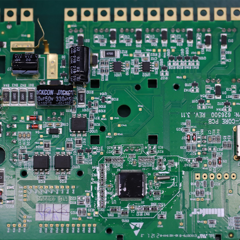
pcb assembling

4.How do surface mount components differ from through-hole components in a PCB?

We pay attention to user experience and product quality, and provide the best product quality and lowest production cost for cooperative customers.
Surface mount components (SMD) and through-hole components (THD) are two different types of electronic components used in printed circuit boards (PCBs). The main difference between them lies in their method of mounting onto the PCB.

1. Mounting Method:
The main difference between SMD and THD components is their mounting method. SMD components are mounted directly onto the surface of the PCB, while THD components are inserted into holes drilled into the PCB and soldered on the other side.

2. Size:
SMD components are generally smaller in size compared to THD components. This is because SMD components do not require leads or pins for mounting, allowing for a more compact design. THD components, on the other hand, have leads or pins that need to be inserted into the PCB, making them larger in size.

3. Space Efficiency:
Due to their smaller size, SMD components allow for a more space-efficient design on the PCB. This is especially important in modern electronic devices where space is limited. THD components take up more space on the PCB due to their larger size and the need for holes to be drilled.

4. Cost:
SMD components are generally more expensive than THD components. This is because SMD components require more advanced manufacturing techniques and equipment, making them costlier to produce.

5. Assembly Process:
The assembly process for SMD components is automated, using pick-and-place machines to accurately place the components onto the PCB. This makes the process faster and more efficient compared to THD components, which require manual insertion and soldering.

6. Electrical Performance:
SMD components have better electrical performance compared to THD components. This is because SMD components have shorter leads, resulting in less parasitic capacitance and inductance, leading to better signal integrity.

In summary, SMD components offer a more compact design, better electrical performance, and a faster assembly process, but at a higher cost. THD components, on the other hand, are larger in size, less expensive, and can handle higher power and voltage ratings. The choice between SMD and THD components depends on the specific requirements of the PCB design and the intended use of the electronic device.

5.Can PCBs be made with different thicknesses?

We operate our pcb assembling business with integrity and honesty.
Yes, PCBs (printed circuit boards) can be made with different thicknesses. The thickness of a PCB is determined by the thickness of the copper layer and the thickness of the substrate material. The copper layer thickness can range from 0.5 oz to 3 oz, while the substrate material thickness can range from 0.2 mm to 3.2 mm. The most common thicknesses for PCBs are 1.6 mm and 0.8 mm, but custom thicknesses can be requested from PCB manufacturers. The thickness of a PCB can affect its mechanical strength, thermal properties, and electrical performance.

6.How does the hole size and shape impact the manufacturing process of a PCB?

We continue to invest in research and development and continue to launch innovative products.
The hole size and shape on a PCB can impact the manufacturing process in several ways:

1. Drilling process: The size and shape of the holes determine the type of drill bit and the drilling speed required for creating the holes. Smaller holes require smaller drill bits and slower drilling speeds, while larger holes require larger drill bits and faster drilling speeds. The shape of the hole can also affect the stability of the drill bit and the accuracy of the drilling process.

2. Plating process: After the holes are drilled, they need to be plated with a conductive material to create electrical connections between different layers of the PCB. The size and shape of the holes can affect the plating process, as larger or irregularly shaped holes may require more plating material and longer plating times.

3. Soldering process: The size and shape of the holes can also impact the soldering process. Smaller holes may require more precise placement of components and more careful soldering techniques, while larger holes may allow for easier soldering.

4. Component placement: The size and shape of the holes can also affect the placement of components on the PCB. Smaller holes may limit the size of components that can be used, while larger holes may allow for more flexibility in component placement.

5. PCB design: The size and shape of the holes can also impact the overall design of the PCB. Different hole sizes and shapes may require different routing and layout strategies, which can affect the overall functionality and performance of the PCB.

Overall, the size and shape of the holes on a PCB can significantly impact the manufacturing process and should be carefully considered during the design phase to ensure efficient and accurate production.
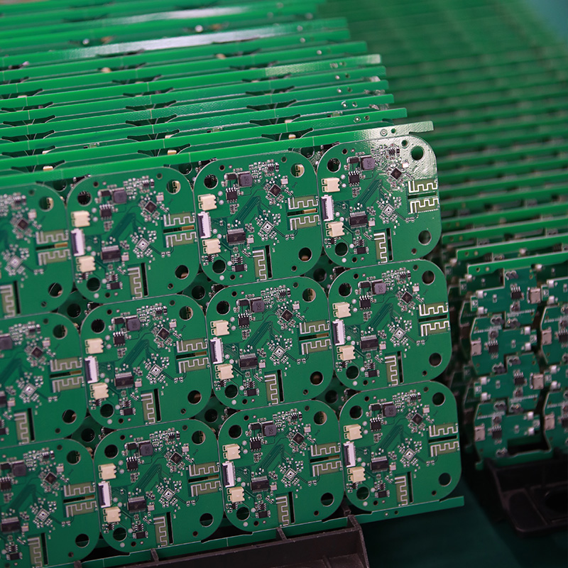
pcb assembling


Tags:circuit board assemblies, flex pcba manufacturer

 

PCBA

For over two decades, MTI has been dedicated to providing comprehensive OEM/ODM manufacturing services to customers worldwide. With our extensive expertise in PCB assembly, we have established strong collaborative relationships with authorized component distributors. This allows us to source any required components at competitive prices, ensuring cost-effectiveness for our clients.

Product name oem rigid flex electronic pcba
Keyword 100 keyboard pcb,smt circuit board assembly,108 keyboard pcb,10 layer pcb fabrication,12v battery charger pcb board
Place of Origin China
Board Thickness 2~3.2mm
Applicable Industries computers and peripherals, etc.
Service OEM/ODM manufacturing
Certificate ISO-9001:2015, ISO-14001:2015,ISO-13485:2012.UL/CSA
Solder Mask Color White
Advantage We keep good quality and competitive price to ensure our customers benefit
Sales country All over the world for example:Tunisia,Papua New Guinea,Aruba,Chile,Faroe Islands,Cyprus,Singapore


One of our Hardware Design Services is small-batch manufacturing, which allows you to test your idea quickly and verify the functionality of the hardware design and PCB board.

Your deliverables are always ahead of schedule and of the highest quality.

We have rich experience engineer to create a layout using a software platform like Altium Designer. This layout shows you the exact appearance and placement of the components on your board.

FAQs Guide

1.How do surface mount components differ from through-hole components in a PCB?

We pay attention to user experience and product quality, and provide the best product quality and lowest production cost for cooperative customers.
Surface mount components (SMD) and through-hole components (THD) are two different types of electronic components used in printed circuit boards (PCBs). The main difference between them lies in their method of mounting onto the PCB.

1. Mounting Method:
The main difference between SMD and THD components is their mounting method. SMD components are mounted directly onto the surface of the PCB, while THD components are inserted into holes drilled into the PCB and soldered on the other side.

2. Size:
SMD components are generally smaller in size compared to THD components. This is because SMD components do not require leads or pins for mounting, allowing for a more compact design. THD components, on the other hand, have leads or pins that need to be inserted into the PCB, making them larger in size.

3. Space Efficiency:
Due to their smaller size, SMD components allow for a more space-efficient design on the PCB. This is especially important in modern electronic devices where space is limited. THD components take up more space on the PCB due to their larger size and the need for holes to be drilled.

4. Cost:
SMD components are generally more expensive than THD components. This is because SMD components require more advanced manufacturing techniques and equipment, making them costlier to produce.

5. Assembly Process:
The assembly process for SMD components is automated, using pick-and-place machines to accurately place the components onto the PCB. This makes the process faster and more efficient compared to THD components, which require manual insertion and soldering.

6. Electrical Performance:
SMD components have better electrical performance compared to THD components. This is because SMD components have shorter leads, resulting in less parasitic capacitance and inductance, leading to better signal integrity.

In summary, SMD components offer a more compact design, better electrical performance, and a faster assembly process, but at a higher cost. THD components, on the other hand, are larger in size, less expensive, and can handle higher power and voltage ratings. The choice between SMD and THD components depends on the specific requirements of the PCB design and the intended use of the electronic device.

2.Can OEM rigid flex electronic pcba be designed to withstand high vibration or shock?

We have established long-term and stable partnerships with our suppliers, so we have great advantages in price and cost and quality assurance.
Yes, PCBs can be designed to withstand high vibration or shock by incorporating certain design features and using appropriate materials. Some ways to make a PCB more resistant to vibration and shock include:

1. Using a thicker and more rigid PCB substrate material, such as FR-4 or ceramic, to provide better structural support and reduce flexing.

2. Adding additional support structures, such as mounting holes or stiffeners, to secure the PCB to the chassis or enclosure.

3. Using smaller and more compact components to reduce the overall weight and size of the PCB, which can help minimize the effects of vibration.

4. Using shock-absorbing materials, such as rubber or foam, between the PCB and the mounting surface to absorb and dampen vibrations.

5. Designing the PCB layout to minimize the length and number of traces and vias, which can reduce the risk of mechanical stress and failure.

6. Using surface mount technology (SMT) components instead of through-hole components, as they are less prone to damage from vibration.

7. Incorporating conformal coating or potting materials to protect the PCB and components from moisture and mechanical stress.

It is important to consider the specific requirements and environment in which the PCB will be used when designing for high vibration or shock resistance. Consulting with a PCB design expert can also help ensure that the PCB is properly designed to withstand these conditions.

Can PCBs be designed to withstand high vibration or shock?

3.Can OEM rigid flex electronic pcba have multiple power planes?

We maintain a stable growth through reasonable capital operations, focus on industry development trends and cutting -edge technologies, and focus on product quality and safety performance.
Yes, PCBs can have multiple power planes. Power planes are layers of copper on a PCB that are used to distribute power and ground signals throughout the board. Multiple power planes can be used to provide different voltages or to separate sensitive analog signals from noisy digital signals. They can also be used to increase the current carrying capacity of the board. The number and arrangement of power planes on a PCB will depend on the specific design requirements and can vary greatly.

4.How does the type of PCB connection (wired or wireless) impact its design and features?

Our products & services cover a wide range of areas and meet the needs of different fields.
The type of PCB connection, whether wired or wireless, can have a significant impact on the design and features of the PCB. Some of the key ways in which the type of connection can impact the PCB design and features are:

1. Size and form factor: Wired PCBs typically require physical connectors and cables, which can add to the overall size and form factor of the PCB. On the other hand, wireless PCBs do not require physical connectors and cables, allowing for a smaller and more compact design.

2. Power consumption: Wired PCBs require a constant supply of power to function, whereas wireless PCBs can operate on battery power. This can impact the power consumption and battery life of the device, which in turn can affect the overall design and features of the PCB.

3. Flexibility and mobility: Wireless PCBs offer greater flexibility and mobility as they do not have physical connections that restrict movement. This can be advantageous in applications where the device needs to be moved or used in different locations.

4. Data transfer speed: Wired PCBs typically have faster data transfer speeds compared to wireless PCBs. This can impact the design and features of the PCB, as certain applications may require high-speed data transfer.

5. Cost: The type of connection can also impact the cost of the PCB. Wired PCBs may require additional components such as connectors and cables, which can add to the overall cost. Wireless PCBs, on the other hand, may require more advanced technology and components, making them more expensive.

6. Reliability: Wired PCBs are generally considered more reliable as they have a physical connection, which is less prone to interference or signal loss. Wireless PCBs, on the other hand, may be more susceptible to interference and signal loss, which can impact their reliability.

Overall, the type of PCB connection can significantly impact the design and features of the PCB, and it is important to carefully consider the specific requirements of the application when choosing between wired and wireless connections.

OEM rigid flex electronic pcba

5.How does the type of PCB finish affect its durability and lifespan?

I have a comprehensive after -sales service system, which can pay attention to market trends in time and adjust our strategy in a timely manner.

The type of OEM rigid flex electronic pcba finish can have a significant impact on the durability and lifespan of a PCB. The finish is the final coating applied to the surface of the PCB to protect it from environmental factors and ensure proper functionality. Some common types of PCB finishes include HASL (Hot Air Solder Leveling), ENIG (Electroless Nickel Immersion Gold), and OSP (Organic Solderability Preservative).

1. HASL (Hot Air Solder Leveling):
HASL is a popular and cost-effective finish that involves coating the PCB with a layer of molten solder and then leveling it with hot air. This finish provides good solderability and is suitable for most applications. However, it is not very durable and can be prone to oxidation, which can affect the performance of the PCB over time. HASL finish also has a limited shelf life and may require rework after a certain period.

2. ENIG (Electroless Nickel Immersion Gold):
ENIG is a more advanced and durable finish compared to HASL. It involves depositing a layer of nickel and then a layer of gold on the surface of the PCB. This finish provides excellent corrosion resistance and is suitable for high-reliability applications. ENIG finish also has a longer shelf life and does not require rework as frequently as HASL.

3. OSP (Organic Solderability Preservative):
OSP is a thin organic coating applied to the surface of the PCB to protect it from oxidation. It is a cost-effective finish and provides good solderability. However, OSP finish is not as durable as ENIG and may require rework after a certain period. It is also not suitable for high-temperature applications.

In summary, the type of PCB finish can affect its durability and lifespan in the following ways:

– Corrosion resistance: Finishes like ENIG and OSP provide better corrosion resistance compared to HASL, which can affect the performance and lifespan of the OEM rigid flex electronic pcba.
– Shelf life: Finishes like ENIG have a longer shelf life compared to HASL, which may require rework after a certain period.
– Solderability: All finishes provide good solderability, but ENIG and OSP are more suitable for high-reliability applications.
– Environmental factors: The type of finish can also affect the PCB’s resistance to environmental factors like humidity, temperature, and chemicals, which can impact its durability and lifespan.

In conclusion, choosing the right type of PCB finish is crucial for ensuring the durability and longevity of the PCB. Factors such as the application, environmental conditions, and budget should be considered when selecting the appropriate finish for a PCB.

6.What materials are commonly used to make PCBs?

We have advantages in marketing and channel expansion. Suppliers have established good cooperative relations, continuously improved workflows, improved efficiency and productivity, and provided customers with high -quality products and services.
1. Copper: Copper is the most commonly used material for PCBs. It is used as the conductive layer for the circuit traces and pads.

2. FR4: FR4 is a type of fiberglass-reinforced epoxy laminate that is used as the base material for most PCBs. It provides good mechanical strength and insulation properties.

3. Solder mask: Solder mask is a layer of polymer that is applied over the copper traces to protect them from oxidation and to prevent solder bridges during assembly.

4. Silkscreen: Silkscreen is a layer of ink that is printed on top of the solder mask to provide component labels, reference designators, and other information.

5. Tin/lead or lead-free solder: Solder is used to attach components to the PCB and to create electrical connections between them.

6. Gold: Gold is used for plating the contact pads and vias on the PCB, as it provides good conductivity and corrosion resistance.

7. Silver: Silver is sometimes used as an alternative to gold for plating contact pads and vias, as it is cheaper but still provides good conductivity.

8. Nickel: Nickel is used as a barrier layer between the copper and gold or silver plating to prevent them from diffusing into each other.

9. Epoxy resin: Epoxy resin is used as an adhesive to bond the layers of the PCB together.

10. Ceramic: Ceramic materials are used for specialized PCBs that require high thermal conductivity and insulation properties, such as in high-power applications.

OEM rigid flex electronic pcba


Tags:108 keyboard pcb,china rigid flex electronic pcba


PCBA

MTI, a leading PCB assembly manufacturer, is committed to delivering high-quality printed circuit boards (PCBs) efficiently and cost-effectively. One critical factor in achieving this goal is reducing lead times in PCB manufacturing. This article explores how MTI optimizes lead times to lower manufacturing costs, highlighting the strategies, benefits, and impact on overall production efficiency.

Introduction to Lead Times in PCB Manufacturing

Importance of Lead Times

Definition and Overview

Lead time in PCB manufacturing refers to the total time taken from the initial order placement to the final delivery of the product. It encompasses various stages, including design, prototyping, production, and testing.

Impact on Costs

Long lead times can increase manufacturing costs due to extended labor, operational expenses, and potential delays in project timelines. Reducing lead times is crucial for improving cost efficiency and meeting market demands promptly.

Strategies for Reducing Lead Times at MTI

Streamlined Design Processes

Early Design Review

MTI conducts early design reviews to identify and resolve potential issues before they progress to the manufacturing stage. This proactive approach minimizes rework and reduces the time spent on design iterations.

Design for Manufacturability (DFM)

Incorporating DFM principles ensures that the PCB design is optimized for efficient manufacturing. This strategy reduces complexities, enhances production speed, and minimizes errors.

Advanced Prototyping Techniques

Rapid Prototyping

MTI utilizes rapid prototyping techniques to accelerate the development of PCB prototypes. By employing advanced tools and technologies, we can quickly produce and test prototypes, shortening the overall development cycle.

In-House Prototyping Capabilities

Having in-house prototyping capabilities allows MTI to control the entire process, reducing dependency on external suppliers and eliminating associated delays.

Efficient Production Processes

Automation and Robotics

Integrating automation and robotics in production processes enhances precision and speed. Automated systems streamline tasks such as component placement, soldering, and inspection, significantly reducing lead times.

Just-In-Time (JIT) Manufacturing

MTI employs JIT manufacturing principles to minimize inventory costs and ensure timely production. By synchronizing production schedules with demand, we reduce the waiting time for materials and components.

Optimized Supply Chain Management

Strong Supplier Relationships

MTI maintains strong relationships with reliable suppliers to ensure a steady and timely supply of materials and components. This collaboration minimizes delays and disruptions in the supply chain.

Real-Time Inventory Management

Implementing real-time inventory management systems allows us to monitor stock levels, track orders, and anticipate material requirements accurately. This system helps prevent shortages and reduces lead times.

Quality Control and Testing

Automated Testing

Automated testing processes, such as Automated Optical Inspection (AOI) and In-Circuit Testing (ICT), speed up the quality assurance phase. These technologies ensure that PCBs meet stringent quality standards without manual intervention delays.

Continuous Improvement

MTI is committed to continuous improvement, regularly reviewing and refining our processes to enhance efficiency and reduce lead times further. This commitment ensures that we remain competitive and responsive to market needs.

PCBA

PCB Assembly

Benefits of Reducing Lead Times

Cost Reduction

Lower Labor Costs

Shorter lead times reduce the amount of labor required for each project, lowering overall labor costs. Efficient processes also reduce overtime and associated expenses.

Reduced Operational Costs

Optimizing lead times minimizes the operational costs associated with extended production cycles, such as energy consumption, equipment wear and tear, and facility overheads.

Enhanced Competitiveness

Faster Time-to-Market

Reducing lead times allows MTI to deliver products to market faster, giving our clients a competitive edge. Quick turnaround times enable businesses to capitalize on market opportunities promptly.

Increased Customer Satisfaction

Timely delivery of high-quality PCBs enhances customer satisfaction and builds trust. Satisfied customers are more likely to return for future projects and recommend MTI to others.

Improved Production Efficiency

Higher Throughput

Efficient processes and reduced lead times increase the throughput of our manufacturing facilities. This improvement allows MTI to handle more projects simultaneously, maximizing production capacity.

Flexibility and Adaptability

Shorter lead times provide greater flexibility in responding to changes in customer requirements or market conditions. MTI can adapt quickly to new demands, ensuring continuous alignment with client needs.

MTI’s Commitment to Reducing Lead Times

Investment in Technology

Cutting-Edge Equipment

MTI invests in state-of-the-art equipment and technologies to streamline production processes and reduce lead times. Our advanced machinery ensures precision, speed, and reliability in PCB manufacturing.

Research and Development

Our dedicated R&D team continuously explores new methodologies and technologies to improve manufacturing efficiency. This focus on innovation drives our ability to reduce lead times and enhance cost-effectiveness.

Skilled Workforce

Training and Development

MTI prioritizes the training and development of our workforce, ensuring that our team is skilled in the latest manufacturing techniques and technologies. A knowledgeable team is crucial for maintaining efficient operations and reducing lead times.

Collaborative Culture

We foster a collaborative culture where employees work together to identify and implement process improvements. This collective effort enhances our ability to reduce lead times and deliver high-quality products.

Conclusion

Reducing lead times is a critical factor in lowering PCB manufacturing costs and enhancing overall production efficiency. MTI employs a comprehensive approach that includes streamlined design processes, advanced prototyping, efficient production methods, optimized supply chain management, and rigorous quality control. By continuously investing in technology and our skilled workforce, MTI remains committed to delivering high-quality PCBs with reduced lead times, providing our clients with cost-effective solutions and a competitive advantage. Trust MTI, a leading PCB assembly manufacturer, to meet your PCB needs with efficiency and excellence.

MTI is a professional manufacturer of PCB and PCBA , we supply one-stop service. The company’s main services include PCB production, PCB Assembly and electronic materials purchasing, SMT patch, circuit board welding, circuit board plug-in.

Our clientele spans across major continents (Africa,Europe,America)and encompasses various industries, including healthcare,military

Product name h60 pcb
Keyword 10 pin pcb connector,printed circuit board assemblies,007 pcb,eft pcb
Place of Origin China
Board Thickness 1~3.2mm
Applicable Industries military, etc.
Service OEM/ODM manufacturing
Certificate ISO-9001:2015, ISO-14001:2015,ISO-13485:2012.UL/CSA
Solder Mask Color White
Advantage We keep good quality and competitive price to ensure our customers benefit
Sales country All over the world for example:Romania,Congo, Republic of the,Panama,Yemen,Sri Lanka,Jersey,Mali


One of our Hardware Design Services is small-batch manufacturing, which allows you to test your idea quickly and verify the functionality of the hardware design and PCB board.

Your deliverables are always ahead of schedule and of the highest quality.

We have rich experience engineer to create a layout using a software platform like Altium Designer. This layout shows you the exact appearance and placement of the components on your board.

FAQs Guide

1.What are the factors to consider when choosing the right PCB material for a specific application?

We are centered on customers and always pay attention to customers’ needs for h60 pcb products.
1. Electrical properties: The electrical properties of the PCB material, such as dielectric constant, loss tangent, and insulation resistance, should be carefully considered to ensure optimal performance for the specific application.

2. Thermal properties: The thermal conductivity and coefficient of thermal expansion of the PCB material are important factors to consider, especially for applications that require high power or operate in extreme temperatures.

3. Mechanical properties: The mechanical strength, stiffness, and flexibility of the PCB material should be evaluated to ensure it can withstand the physical stresses and strains of the application.

4. Chemical resistance: The PCB material should be resistant to any chemicals or solvents that it may come into contact with during its use.

5. Cost: The cost of the PCB material should be considered, as it can vary significantly depending on the type and quality of the material.

6. Availability: Some PCB materials may be more readily available than others, which can affect production timelines and costs.

7. Manufacturing process: The chosen PCB material should be compatible with the manufacturing process, such as etching, drilling, and plating, to ensure efficient and reliable production.

8. Environmental factors: The application environment, such as humidity, moisture, and exposure to UV light, should be taken into account when selecting a PCB material to ensure it can withstand these conditions.

9. Signal integrity: For high-frequency applications, the PCB material should have low signal loss and good signal integrity to prevent interference and ensure accurate signal transmission.

10. RoHS compliance: If the application requires compliance with environmental regulations, such as the Restriction of Hazardous Substances (RoHS) directive, the PCB material should be chosen accordingly.

2.Can a PCB have different levels of flexibility?

We have a wide range of h60 pcb customer groups and establishes long -term cooperative relationships with partners.
Yes, a PCB (printed circuit board) can have different levels of flexibility depending on its design and materials used. Some PCBs are rigid and cannot bend or flex at all, while others are designed to be flexible and can bend or twist to a certain degree. There are also PCBs that have a combination of rigid and flexible areas, known as flex-rigid PCBs. The level of flexibility in a PCB is determined by factors such as the type of substrate material, the thickness and number of layers, and the type of circuit design.

3.What is the minimum distance required between components on a PCB?

We have advanced production equipment and technology to meet the needs of customers, and can provide customers with high quality, low priced h60 pcb products.
The minimum distance required between components on a PCB depends on various factors such as the type of components, their size, and the manufacturing process used. Generally, the minimum distance between components is determined by the manufacturer’s design rules and guidelines.

For surface mount components, the minimum distance between components is typically 0.2mm to 0.3mm. This distance is necessary to ensure that the solder paste does not bridge between the pads during the reflow process.

For through-hole components, the minimum distance between components is typically 1mm to 2mm. This distance is necessary to ensure that the components do not interfere with each other during the assembly process.

In high-speed and high-frequency applications, the minimum distance between components may need to be increased to avoid signal interference and crosstalk. In these cases, the manufacturer’s design rules and guidelines should be followed closely.

Overall, the minimum distance between components on a PCB should be determined based on the specific requirements of the design and the capabilities of the manufacturing process.

What is the minimum distance required between components on a PCB?

4.Can PCBs be made with different thicknesses?

We operate our h60 pcb business with integrity and honesty.
Yes, PCBs (printed circuit boards) can be made with different thicknesses. The thickness of a PCB is determined by the thickness of the copper layer and the thickness of the substrate material. The copper layer thickness can range from 0.5 oz to 3 oz, while the substrate material thickness can range from 0.2 mm to 3.2 mm. The most common thicknesses for PCBs are 1.6 mm and 0.8 mm, but custom thicknesses can be requested from PCB manufacturers. The thickness of a PCB can affect its mechanical strength, thermal properties, and electrical performance.

5.Can PCBs have different shapes and sizes?

Our company has many years of h60 pcb experience and expertise.
Yes, PCBs (printed circuit boards) can have different shapes and sizes depending on the specific design and purpose of the circuit. They can range from small and compact to large and complex, and can be rectangular, circular, or even irregularly shaped. The shape and size of a PCB is determined by the layout of the components and the desired functionality of the circuit.

6.Can PCBs be designed with high-speed and high-frequency applications in mind?

We attach importance to the innovation ability and team spirit of employees, have advanced R & D facilities and laboratories, and have a good quality management system.
Yes, PCBs can be designed with high-speed and high-frequency applications in mind. This involves careful consideration of the layout, trace routing, and component placement to minimize signal loss and interference. Specialized materials and techniques, such as controlled impedance routing and differential pairs, can also be used to improve signal integrity and reduce noise. Additionally, the use of advanced simulation and analysis tools can help optimize the design for high-speed and high-frequency performance.

Can PCBs be designed with high-speed and high-frequency applications in mind?

7.How does the type of vias used affect the performance of a PCB?

Being one of the top h60 pcb manufacturers in China, We attach great importance to this detail.
The type of vias used can affect the performance of a PCB in several ways:

1. Signal Integrity: Vias can act as discontinuities in the signal path, causing reflections and signal degradation. The type of via used can impact the impedance and signal integrity of the PCB. For high-speed signals, it is important to use controlled impedance vias to maintain signal integrity.

2. Electrical Performance: The type of via used can also affect the electrical performance of the PCB. For example, through-hole vias have lower resistance and inductance compared to blind or buried vias, which can affect the power delivery and signal transmission on the PCB.

3. Thermal Performance: Vias can also play a role in the thermal performance of a PCB. Through-hole vias can act as thermal vias, allowing heat to dissipate from one layer to another. Blind and buried vias, on the other hand, can trap heat and affect the overall thermal management of the PCB.

4. Manufacturing Cost: The type of via used can also impact the cost of manufacturing the PCB. Blind and buried vias require more complex and expensive processes, while through-hole vias are relatively simpler and cheaper to manufacture.

5. PCB Size and Density: The type of via used can also affect the size and density of the PCB. Blind and buried vias take up less space on the surface of the PCB, allowing for higher density designs. This can be beneficial for smaller and more compact PCBs.

Overall, the type of vias used can have a significant impact on the performance, cost, and design of a PCB. It is important to carefully consider the type of vias needed for a specific application to ensure optimal performance and functionality of the PCB.

8.How do PCBs support the integration of different electronic components?

We actively participate in the h60 pcb industry associations and organization activities. The corporate social responsibility performed well, and the focus of brand building and promotion.
PCBs (Printed Circuit Boards) are essential for the integration of different electronic components in electronic devices. They provide a platform for connecting and supporting the various components, allowing them to work together seamlessly. Here are some ways in which PCBs support the integration of different electronic components:

1. Electrical connections: PCBs have a network of copper traces that connect the different electronic components on the board. These traces act as conductors, allowing electricity to flow between the components and enabling them to communicate and work together.

2. Mounting surface: PCBs provide a stable and secure mounting surface for electronic components. The components are soldered onto the board, ensuring that they are firmly attached and will not move or become loose during operation.

3. Space-saving: PCBs are designed to be compact and space-saving, allowing for the integration of multiple components on a single board. This is especially useful in small electronic devices where space is limited.

4. Customization: PCBs can be customized to accommodate different types and sizes of electronic components. This allows for flexibility in design and the integration of a wide range of components, making it easier to create complex electronic devices.

5. Signal routing: PCBs have multiple layers, with each layer dedicated to a specific function. This allows for efficient routing of signals between components, reducing interference and ensuring that the components can communicate effectively.

6. Power distribution: PCBs have dedicated power planes that distribute power to the different components on the board. This ensures that each component receives the required amount of power, preventing damage and ensuring proper functioning.

7. Thermal management: PCBs also play a crucial role in managing the heat generated by electronic components. They have copper layers that act as heat sinks, dissipating heat and preventing the components from overheating.

In summary, PCBs provide a robust and efficient platform for integrating different electronic components. They enable the components to work together seamlessly, ensuring the proper functioning of electronic devices.


Tags:printed circuit assembly,pcb circuit board,flex pcba manufacturer,12 layer pcb


MTI is a high-tech company specializing in PCB manufacturing, PCB assembly and parts procurement services with more than 20 years of experience. We are committed to producing various types of printed circuit boards, mainly including single-sided, double-sided, multi-layer circuit boards, high-precision HDI, flexible boards (FPC), rigid-flex boards (including HDI), metal circuit boards and their SMD plugin.Product line application areas include:aerospace.Fast response, strict quality control, best service, and strong technical support export our PCB products to global markets,including,Dominica,Haiti,Lebanon,Papua New Guinea,Israel.

MTI would like to build long and stable business relationship with the customers from all over the world on the basis of mutual benefits and mutual progress;Choose MTI , Drive you Success!

Product name gh60 pcb
Keyword 12 layer pcb thickness,printed circuit board assembly process
Place of Origin China
Board Thickness 1~3.2mm
Applicable Industries aerospace, etc.
Service OEM/ODM manufacturing
Certificate ISO-9001:2015, ISO-14001:2015,ISO-13485:2012.UL/CSA
Solder Mask Color Green
Advantage We keep good quality and competitive price to ensure our customers benefit
Sales country All over the world for example:Dominica,Haiti,Lebanon,Papua New Guinea,Israel


We have rich experience engineer to create a layout using a software platform like Altium Designer. This layout shows you the exact appearance and placement of the components on your board.

One of our Hardware Design Services is small-batch manufacturing, which allows you to test your idea quickly and verify the functionality of the hardware design and PCB board.

Your deliverables are always ahead of schedule and of the highest quality.

FAQs Guide

1.What is testability in PCB design and how is it achieved?

Our gh60 pcb products undergo strict quality control to ensure customer satisfaction.
Testability in PCB design refers to the ease and accuracy with which a printed circuit board (PCB) can be tested for functionality and performance. It is an important aspect of PCB design as it ensures that any defects or issues with the board can be identified and addressed before it is put into use.

Achieving testability in PCB design involves implementing certain design features and techniques that make it easier to test the board. These include:

1. Design for Test (DFT): This involves designing the PCB with specific test points and access points that allow for easy and accurate testing of different components and circuits.

2. Test Points: These are designated points on the PCB where test probes can be connected to measure voltage, current, and other parameters. Test points should be strategically placed to provide access to critical components and circuits.

3. Test Pads: These are small copper pads on the PCB that are used for attaching test probes. They should be placed close to the corresponding component or circuit for accurate testing.

4. Test Jigs: These are specialized tools used for testing PCBs. They can be custom-made for a specific PCB design and can greatly improve the accuracy and efficiency of testing.

5. Design for Manufacturability (DFM): This involves designing the PCB with manufacturing and testing in mind. This includes using standard components, avoiding complex layouts, and minimizing the number of layers to make testing easier.

6. Design for Debug (DFD): This involves designing the PCB with features that make it easier to identify and troubleshoot any issues that may arise during testing.

Overall, achieving testability in PCB design requires careful planning and consideration of the testing process. By implementing DFT, using test points and pads, and designing for manufacturability and debug, designers can ensure that their PCBs are easily testable and can be quickly and accurately diagnosed for any potential issues.

2.What are the differences between a prototype and production PCB?

We have a good reputation and image in the industry. The quality and price advantage of gh60 pcb products is an important factor in our hard overseas market.
1. Purpose: The main difference between a prototype and production PCB is their purpose. A prototype PCB is used for testing and validation of a design, while a production PCB is used for mass production and commercial use.

2. Design: Prototype PCBs are usually hand-soldered and have a simpler design compared to production PCBs. Production PCBs are designed with more precision and complexity to meet the specific requirements of the final product.

3. Materials: Prototype PCBs are often made with cheaper materials such as FR-4, while production PCBs use higher quality materials such as ceramic or metal core for better performance and durability.

4. Quantity: Prototype PCBs are usually made in small quantities, while production PCBs are manufactured in large quantities to meet the demand of the market.

5. Cost: Due to the use of cheaper materials and smaller quantities, prototype PCBs are less expensive compared to production PCBs. Production PCBs require a larger investment due to the use of higher quality materials and larger quantities.

6. Lead time: Prototype PCBs have a shorter lead time as they are made in smaller quantities and can be hand-soldered. Production PCBs have a longer lead time as they require more complex manufacturing processes and larger quantities.

7. Testing: Prototype PCBs are extensively tested to ensure the design is functional and meets the required specifications. Production PCBs also undergo testing, but the focus is more on quality control and consistency in mass production.

8. Documentation: Prototype PCBs may not have detailed documentation as they are often hand-soldered and used for testing purposes. Production PCBs have detailed documentation to ensure consistency in manufacturing and for future reference.

9. Modifications: Prototype PCBs are easier to modify and make changes to, as they are not mass-produced. Production PCBs are more difficult to modify as any changes can affect the entire production process.

10. Reliability: Production PCBs are designed and manufactured to be more reliable and durable, as they will be used in the final product. Prototype PCBs may not have the same level of reliability as they are used for testing and may not undergo the same level of quality control.

3.What materials are commonly used to make PCBs?

We have advantages in marketing and channel expansion. Suppliers have established good cooperative relations, continuously improved workflows, improved efficiency and productivity, and provided customers with high -quality products and services.
1. Copper: Copper is the most commonly used material for PCBs. It is used as the conductive layer for the circuit traces and pads.

2. FR4: FR4 is a type of fiberglass-reinforced epoxy laminate that is used as the base material for most PCBs. It provides good mechanical strength and insulation properties.

3. Solder mask: Solder mask is a layer of polymer that is applied over the copper traces to protect them from oxidation and to prevent solder bridges during assembly.

4. Silkscreen: Silkscreen is a layer of ink that is printed on top of the solder mask to provide component labels, reference designators, and other information.

5. Tin/lead or lead-free solder: Solder is used to attach components to the PCB and to create electrical connections between them.

6. Gold: Gold is used for plating the contact pads and vias on the PCB, as it provides good conductivity and corrosion resistance.

7. Silver: Silver is sometimes used as an alternative to gold for plating contact pads and vias, as it is cheaper but still provides good conductivity.

8. Nickel: Nickel is used as a barrier layer between the copper and gold or silver plating to prevent them from diffusing into each other.

9. Epoxy resin: Epoxy resin is used as an adhesive to bond the layers of the PCB together.

10. Ceramic: Ceramic materials are used for specialized PCBs that require high thermal conductivity and insulation properties, such as in high-power applications.

4.What is the difference between single-sided and double-sided PCBs?

Our mission is to provide customers with the best solutions for gh60 pcb.
Single-sided PCBs have copper traces and components on only one side of the board, while double-sided PCBs have copper traces and components on both sides of the board. This allows for more complex circuit designs and a higher density of components on a double-sided PCB. Single-sided PCBs are typically used for simpler circuits and are less expensive to manufacture, while double-sided PCBs are used for more complex circuits and are more expensive to manufacture.

gh60 pcb

5.How does the number of layers in a PCB affect its functionality?

We should have a stable supply chain and logistics capabilities, and provide customers with high -quality, low -priced gh60 pcb products.
The number of layers in a PCB (Printed Circuit Board) can affect its functionality in several ways:

1. Complexity: The number of layers in a PCB determines the complexity of the circuit design that can be implemented. More layers allow for more components and connections to be included in the design, making it more complex and versatile.

2. Size: A PCB with more layers can be smaller in size compared to a PCB with fewer layers, as it allows for a more compact layout of components and connections. This is especially important in devices with limited space, such as smartphones and wearables.

3. Signal Integrity: The number of layers in a PCB can also affect the signal integrity of the circuit. More layers allow for better routing of signals, reducing the chances of interference and crosstalk between different components.

4. Power Distribution: PCBs with more layers can have dedicated power and ground planes, which help in distributing power evenly across the circuit. This improves the overall performance and stability of the circuit.

5. Cost: The number of layers in a PCB can also affect its cost. More layers mean more materials and manufacturing processes, which can increase the overall cost of the PCB.

6. Thermal Management: PCBs with more layers can have better thermal management, as they allow for the placement of thermal vias and heat sinks to dissipate heat more efficiently. This is important for high-power applications that generate a lot of heat.

In summary, the number of layers in a PCB can significantly impact its functionality, complexity, size, signal integrity, power distribution, cost, and thermal management. Designers must carefully consider the number of layers required for a PCB based on the specific requirements of the circuit and the device it will be used in.


Tags:100 mechanical keyboard pcb,12 layer pcb stack up


MTI is a professional manufacturer of PCB and PCBA , we supply one-stop service. The company’s main services include PCB production, Flexible pcb board, PCB Assembly, and electronic materials purchasing, SMT patch, circuit board welding, circuit board plug-in.

Our clientele spans across major continents (Asia,Oceania,Europe)and encompasses various industries, including healthcare,medical

Product name flexible pcb board
Keyword 100w amplifier pcb,printed circuits assembly corporation,gh60 pcb,16 layer pcb manufacturer,printed circuits assembly corp
Place of Origin China
Board Thickness 1~3.2mm
Applicable Industries medical, etc.
Service OEM/ODM manufacturing
Certificate ISO-9001:2015, ISO-14001:2015,ISO-13485:2012.UL/CSA
Solder Mask Color Blue
Advantage We keep good quality and competitive price to ensure our customers benefit
Sales country All over the world for example:Cape Verde,Sao Tome and Principe,Mozambique,Dominican Republic,Russia,Brunei,Bhutan,Mauritania


Your deliverables are always ahead of schedule and of the highest quality.

We have rich experience engineer to create a layout using a software platform like Altium Designer. This layout shows you the exact appearance and placement of the components on your board.

One of our Hardware Design Services is small-batch manufacturing, which allows you to test your idea quickly and verify the functionality of the hardware design and PCB board.

FAQs Guide

1.What are the factors to consider when choosing the right PCB material for a specific application?

We are centered on customers and always pay attention to customers’ needs for flexible pcb board products.
1. Electrical properties: The electrical properties of the PCB material, such as dielectric constant, loss tangent, and insulation resistance, should be carefully considered to ensure optimal performance for the specific application.

2. Thermal properties: The thermal conductivity and coefficient of thermal expansion of the PCB material are important factors to consider, especially for applications that require high power or operate in extreme temperatures.

3. Mechanical properties: The mechanical strength, stiffness, and flexibility of the PCB material should be evaluated to ensure it can withstand the physical stresses and strains of the application.

4. Chemical resistance: The PCB material should be resistant to any chemicals or solvents that it may come into contact with during its use.

5. Cost: The cost of the PCB material should be considered, as it can vary significantly depending on the type and quality of the material.

6. Availability: Some PCB materials may be more readily available than others, which can affect production timelines and costs.

7. Manufacturing process: The chosen PCB material should be compatible with the manufacturing process, such as etching, drilling, and plating, to ensure efficient and reliable production.

8. Environmental factors: The application environment, such as humidity, moisture, and exposure to UV light, should be taken into account when selecting a PCB material to ensure it can withstand these conditions.

9. Signal integrity: For high-frequency applications, the PCB material should have low signal loss and good signal integrity to prevent interference and ensure accurate signal transmission.

10. RoHS compliance: If the application requires compliance with environmental regulations, such as the Restriction of Hazardous Substances (RoHS) directive, the PCB material should be chosen accordingly.

2.Can PCBs be designed with high-speed and high-frequency applications in mind?

We attach importance to the innovation ability and team spirit of employees, have advanced R & D facilities and laboratories, and have a good quality management system.
Yes, PCBs can be designed with high-speed and high-frequency applications in mind. This involves careful consideration of the layout, trace routing, and component placement to minimize signal loss and interference. Specialized materials and techniques, such as controlled impedance routing and differential pairs, can also be used to improve signal integrity and reduce noise. Additionally, the use of advanced simulation and analysis tools can help optimize the design for high-speed and high-frequency performance.

3.What materials are commonly used to make PCBs?

We have advantages in marketing and channel expansion. Suppliers have established good cooperative relations, continuously improved workflows, improved efficiency and productivity, and provided customers with high -quality products and services.
1. Copper: Copper is the most commonly used material for PCBs. It is used as the conductive layer for the circuit traces and pads.

2. FR4: FR4 is a type of fiberglass-reinforced epoxy laminate that is used as the base material for most PCBs. It provides good mechanical strength and insulation properties.

3. Solder mask: Solder mask is a layer of polymer that is applied over the copper traces to protect them from oxidation and to prevent solder bridges during assembly.

4. Silkscreen: Silkscreen is a layer of ink that is printed on top of the solder mask to provide component labels, reference designators, and other information.

5. Tin/lead or lead-free solder: Solder is used to attach components to the PCB and to create electrical connections between them.

6. Gold: Gold is used for plating the contact pads and vias on the PCB, as it provides good conductivity and corrosion resistance.

7. Silver: Silver is sometimes used as an alternative to gold for plating contact pads and vias, as it is cheaper but still provides good conductivity.

8. Nickel: Nickel is used as a barrier layer between the copper and gold or silver plating to prevent them from diffusing into each other.

9. Epoxy resin: Epoxy resin is used as an adhesive to bond the layers of the PCB together.

10. Ceramic: Ceramic materials are used for specialized PCBs that require high thermal conductivity and insulation properties, such as in high-power applications.

Flexible pcb board

4.Can PCBs have different shapes and sizes?

Our company has many years of flexible pcb board experience and expertise.
Yes, PCBs (printed circuit boards) can have different shapes and sizes depending on the specific design and purpose of the circuit. They can range from small and compact to large and complex, and can be rectangular, circular, or even irregularly shaped. The shape and size of a PCB is determined by the layout of the components and the desired functionality of the circuit.

5.What is the maximum current a PCB can handle?

We maintain a certain amount of R&D investment every year and continuously improve operational efficiency to provide better services to our cooperative customers.
The maximum current a PCB can handle depends on various factors such as the thickness and width of the copper traces, the type of material used for the PCB, and the ambient temperature. Generally, a standard PCB can handle currents up to 10-20 amps, while high-power PCBs can handle currents up to 50-100 amps. However, it is always recommended to consult with a PCB manufacturer for specific current handling capabilities for a particular PCB design.

6.How do PCBs handle overcurrent and short circuits?

We have a first -class management team, and we pay attention to teamwork to achieve common goals.
PCBs (printed circuit boards) have several mechanisms in place to handle overcurrent and short circuits:

1. Fuses: Fuses are the most common protection mechanism used on PCBs. They are designed to break the circuit when the current exceeds a certain threshold, preventing damage to the components and the board.

2. Circuit breakers: Similar to fuses, circuit breakers are designed to break the circuit when the current exceeds a certain threshold. However, unlike fuses, circuit breakers can be reset and reused.

3. Overcurrent protection devices: These devices, such as overcurrent protection diodes, are designed to limit the amount of current flowing through the circuit. They act as a safety valve, preventing excessive current from damaging the components.

4. Thermal protection: Some PCBs have thermal protection mechanisms, such as thermal fuses or thermal cutoffs, which are designed to break the circuit when the temperature of the board exceeds a certain threshold. This helps prevent damage to the board and components due to overheating.

5. Short circuit protection: PCBs may also have short circuit protection mechanisms, such as polymeric positive temperature coefficient (PPTC) devices, which are designed to limit the current in the event of a short circuit. These devices have a high resistance at normal operating temperatures, but their resistance increases significantly when the temperature rises due to a short circuit, limiting the current flow.

Overall, PCBs use a combination of these protection mechanisms to handle overcurrent and short circuits, ensuring the safety and reliability of the board and its components.

How do Flexible pcb board handle overcurrent and short circuits?

7.What is impedance control and why is it important in PCBs?

We enjoy high authority and influence in the industry and continue to innovate products and service models.
Impedance control is the ability to maintain a consistent electrical impedance throughout a printed circuit board (PCB). It is important in PCBs because it ensures that signals can travel through the board without distortion or loss of quality.

Impedance control is particularly important in high-speed digital and analog circuits, where even small variations in impedance can cause signal reflections and distortions. This can lead to errors in data transmission and affect the overall performance of the circuit.

In addition, impedance control is crucial in ensuring signal integrity and reducing electromagnetic interference (EMI). By maintaining a consistent impedance, the PCB can effectively filter out unwanted signals and prevent them from interfering with the desired signals.

Overall, impedance control is essential for achieving reliable and high-quality performance in PCBs, especially in complex and sensitive electronic systems. It requires careful design and manufacturing techniques, such as controlled trace widths and spacing, to achieve the desired impedance levels.

8.How does the type of PCB connection (wired or wireless) impact its design and features?

Our products & services cover a wide range of areas and meet the needs of different fields.
The type of PCB connection, whether wired or wireless, can have a significant impact on the design and features of the PCB. Some of the key ways in which the type of connection can impact the PCB design and features are:

1. Size and form factor: Wired PCBs typically require physical connectors and cables, which can add to the overall size and form factor of the PCB. On the other hand, wireless PCBs do not require physical connectors and cables, allowing for a smaller and more compact design.

2. Power consumption: Wired PCBs require a constant supply of power to function, whereas wireless PCBs can operate on battery power. This can impact the power consumption and battery life of the device, which in turn can affect the overall design and features of the PCB.

3. Flexibility and mobility: Wireless PCBs offer greater flexibility and mobility as they do not have physical connections that restrict movement. This can be advantageous in applications where the device needs to be moved or used in different locations.

4. Data transfer speed: Wired PCBs typically have faster data transfer speeds compared to wireless PCBs. This can impact the design and features of the PCB, as certain applications may require high-speed data transfer.

5. Cost: The type of connection can also impact the cost of the PCB. Wired PCBs may require additional components such as connectors and cables, which can add to the overall cost. Wireless PCBs, on the other hand, may require more advanced technology and components, making them more expensive.

6. Reliability: Wired PCBs are generally considered more reliable as they have a physical connection, which is less prone to interference or signal loss. Wireless PCBs, on the other hand, may be more susceptible to interference and signal loss, which can impact their reliability.

Overall, the type of PCB connection can significantly impact the design and features of the PCB, and it is important to carefully consider the specific requirements of the application when choosing between wired and wireless connections.


Tags:printed circuit board assembly suppliers,12 layer pcb thickness


ntegrating the ESP8266 Wi-Fi module with a PCB layout can significantly enhance your IoT projects. In this detailed guide, we will walk you through the process, leveraging MTI’s expertise as a leading PCB assembly manufacturer. Whether you’re an OEM/ODM seeking optimized designs or a wholesaler looking for reliable supply, this guide is for you.

Understanding the Basics of ESP8266

The ESP8266 is a low-cost Wi-Fi microchip with full TCP/IP stack and microcontroller capability, perfect for IoT applications. Before diving into PCB design, it’s essential to grasp the fundamentals of this versatile module.

Features of ESP8266

  • Low Power Consumption: Ideal for battery-operated applications.
  • High Integration: On-chip processing and storage capabilities.
  • Wide Range of Applications: From home automation to industrial automation.

Designing Your PCB Layout for ESP8266

Designing a PCB layout for the ESP8266 involves several key steps. This section outlines the process, ensuring optimal performance and ease of manufacturing.

Step 1: Schematic Design

Start by creating a schematic diagram. This blueprint will serve as the foundation for your PCB layout.

Tips for Effective Schematic Design

  • Component Placement: Ensure that the ESP8266 and other components are strategically placed for minimal signal interference.
  • Power Supply: Design a robust power supply circuit to ensure stable operation.

Step 2: PCB Layout Design

Once your schematic is ready, you can move on to the PCB layout design.

Key Considerations for PCB Layout

  • Trace Width and Spacing: Maintain appropriate trace widths and spacing to avoid signal crosstalk.
  • Ground Planes: Implement ground planes to reduce noise and improve signal integrity.
  • Thermal Management: Design for adequate heat dissipation, especially in high-power applications.

Step 3: Prototyping

Before mass production, prototyping your PCB design is crucial. MTI offers comprehensive prototyping services to ensure your design meets all specifications.

Benefits of Prototyping with MTI

  • Rapid Turnaround: Quick prototyping to accelerate your R&D process.
  • Cost-Effective: Competitive pricing for high-quality prototypes.
  • Expert Support: Access to MTI’s team of experienced engineers for design optimization.

Manufacturing Your PCB

With your design validated through prototyping, it’s time to move to the manufacturing phase.

Choosing the Right Manufacturer

Selecting a reliable PCB assembly manufacturer like MTI ensures quality and efficiency.

Advantages of MTI’s Manufacturing Services

  • State-of-the-Art Facilities: Equipped with the latest technology for precise manufacturing.
  • Quality Assurance: Rigorous testing and quality control processes.
  • Global Supply Chain: Efficient supply chain management to ensure timely delivery.

Step 4: Assembly

MTI provides comprehensive PCB assembly services, from component sourcing to final assembly.

Key Assembly Services

  • Surface Mount Technology (SMT): Advanced SMT lines for high-precision assembly.
  • Through-Hole Technology: Reliable through-hole assembly for robust connections.
  • Inspection and Testing: In-depth testing to ensure functionality and reliability.

Step 5: Final Testing and Quality Control

Ensuring the final product meets all specifications is crucial. MTI’s rigorous quality control processes guarantee that your PCBs are ready for deployment.

Quality Control Measures

  • Automated Optical Inspection (AOI): High-precision inspection to detect defects.
  • In-Circuit Testing (ICT): Comprehensive testing to verify electrical performance.
  • Functional Testing: Ensuring the final product operates as intended in real-world conditions.

Partnering with MTI for Your ESP8266 Projects

By partnering with MTI, you gain access to a wealth of resources and expertise. Whether you’re an OEM/ODM, supplier, or distributor, MTI’s end-to-end services ensure the success of your ESP8266 projects.

Why Choose MTI?

  • Experienced Team: Decades of experience in PCB design and manufacturing.
  • Competitive Advantage: High-quality products with excellent cost performance.
  • Global Reach: Efficient supply chains and distribution networks.

Conclusion

Integrating the ESP8266 with a PCB layout is a critical step in developing robust IoT solutions. By following this step-by-step guide and leveraging MTI’s manufacturing expertise, you can achieve optimal performance and reliability for your projects. Whether you are looking for a reliable PCB assembly manufacturer, a trusted supplier, or an experienced partner for R&D, MTI is here to support your needs.

Start your journey with MTI today and transform your ideas into reality with superior PCB solutions

pcb

Introduction to MTI: Leading PCB Assembly Manufacturer

MTI is a premier PCB assembly (PCBA) manufacturer, renowned for its high-quality products and exceptional customer service. In addition to PCB assembly, MTI offers professional PCB copy services to meet the diverse needs of its clients. This article provides a comprehensive guide on where to find professional PCB copy services and the benefits of choosing MTI for this critical task.

Understanding PCB Copy Services

What is PCB Copy Service?

PCB copy service, also known as PCB cloning or duplication, involves replicating an existing PCB design. This service is essential for businesses looking to reverse engineer a PCB, update an existing design, or produce additional units of a specific PCB.

Importance of Professional PCB Copy Service

Professional PCB copy services ensure accurate replication of the original design, maintaining the integrity and functionality of the PCB. Precision and expertise are crucial in this process to avoid errors that could impact the performance of the final product.

Why Choose MTI for PCB Copy Services

Expertise and Experience

Skilled Engineers

MTI boasts a team of skilled engineers with extensive experience in PCB design and manufacturing. Their expertise ensures that every PCB copy is meticulously executed, maintaining the highest standards of quality and accuracy.

Advanced Technology

MTI utilizes state-of-the-art technology in its PCB copy services. Advanced scanning and imaging equipment, combined with sophisticated software, enable precise duplication of even the most complex PCB designs.

pcb

Comprehensive Services

Reverse Engineering

MTI offers comprehensive reverse engineering services to accurately replicate existing PCBs. This involves detailed analysis and reproduction of the PCB layout, components, and functionality, ensuring a perfect match with the original.

Design Optimization

In addition to copying the PCB, MTI can optimize the design for improved performance, manufacturability, and cost efficiency. This service is particularly beneficial for businesses looking to enhance their existing PCB designs.

Quality Assurance

Rigorous Testing

MTI employs rigorous testing procedures to ensure the accuracy and reliability of copied PCBs. Each duplicated PCB undergoes extensive testing, including electrical testing and functional validation, to guarantee it meets the required specifications.

Adherence to Standards

MTI adheres to international quality standards, including ISO 9001 and IPC-A-610. This commitment to quality ensures that every PCB copy service delivered by MTI meets the highest industry standards.

Finding Professional PCB Copy Services

Industry Referrals

Networking

One of the best ways to find professional PCB copy services is through industry referrals. Networking with other professionals in the electronics industry can provide valuable insights and recommendations for reliable service providers like MTI.

Trade Shows and Conferences

Attending trade shows and conferences dedicated to electronics and PCB manufacturing can help you connect with reputable service providers. These events offer opportunities to meet industry experts and learn about the latest advancements in PCB technology.

Online Research

Company Websites

Conducting online research is another effective way to find professional PCB copy services. Visiting the websites of established PCB manufacturers, such as MTI, can provide detailed information about their services, expertise, and capabilities.

Online Directories

Online directories and industry-specific platforms list numerous PCB service providers. These directories often include reviews and ratings from previous clients, helping you make an informed decision.

Partnerships and Agents

Local Agents

Working with local agents who represent reputable PCB manufacturers can streamline the process of finding professional PCB copy services. These agents have in-depth knowledge of the industry and can connect you with trusted providers like MTI.

Global Distributors

Global distributors with established relationships with leading PCB manufacturers can also facilitate access to professional PCB copy services. These distributors often have extensive networks and can recommend reliable service providers.

Benefits of Choosing MTI for PCB Copy Services

Precision and Accuracy

By choosing MTI, you benefit from precision and accuracy in every PCB copy project. Their advanced technology and skilled engineers ensure that each duplicated PCB meets the highest standards of quality.

Comprehensive Support

MTI provides comprehensive support throughout the PCB copy process, from initial consultation to final testing and validation. Their customer-centric approach ensures that your specific requirements are met with professionalism and efficiency.

Competitive Advantage

Partnering with MTI for PCB copy services gives you a competitive advantage in the market. Their high-quality, reliable PCBs enable you to deliver superior products to your customers, enhancing your reputation and market position.

Conclusion

Finding professional PCB copy services is crucial for businesses looking to replicate and optimize their PCB designs. MTI, with its expertise, advanced technology, and commitment to quality, stands out as a leading provider of PCB copy services. Whether through industry referrals, online research, or partnerships with agents and distributors, MTI offers the precision, accuracy, and comprehensive support needed to ensure the success of your PCB projects. Choose MTI for your PCB copy needs and experience unparalleled quality and performance in every duplicated PCB.

Introduction to MTI: Leading PCB Assembly Manufacturer

MTI is a premier PCB assembly (PCBA) manufacturer, renowned for its high-quality products and exceptional customer service. In addition to PCB assembly, MTI offers professional PCB copy services to meet the diverse needs of its clients. This article provides a comprehensive guide on where to find professional PCB copy services and the benefits of choosing MTI for this critical task.

Understanding PCB Copy Services

What is PCB Copy Service?

PCB copy service, also known as PCB cloning or duplication, involves replicating an existing PCB design. This service is essential for businesses looking to reverse engineer a PCB, update an existing design, or produce additional units of a specific PCB.

Importance of Professional PCB Copy Service

Professional PCB copy services ensure accurate replication of the original design, maintaining the integrity and functionality of the PCB. Precision and expertise are crucial in this process to avoid errors that could impact the performance of the final product.

Why Choose MTI for PCB Copy Services

Expertise and Experience

Skilled Engineers

MTI boasts a team of skilled engineers with extensive experience in PCB design and manufacturing. Their expertise ensures that every PCB copy is meticulously executed, maintaining the highest standards of quality and accuracy.

Advanced Technology

MTI utilizes state-of-the-art technology in its PCB copy services. Advanced scanning and imaging equipment, combined with sophisticated software, enable precise duplication of even the most complex PCB designs.

Comprehensive Services

Reverse Engineering

MTI offers comprehensive reverse engineering services to accurately replicate existing PCBs. This involves detailed analysis and reproduction of the PCB layout, components, and functionality, ensuring a perfect match with the original.

Design Optimization

In addition to copying the PCB, MTI can optimize the design for improved performance, manufacturability, and cost efficiency. This service is particularly beneficial for businesses looking to enhance their existing PCB designs.

Quality Assurance

Rigorous Testing

MTI employs rigorous testing procedures to ensure the accuracy and reliability of copied PCBs. Each duplicated PCB undergoes extensive testing, including electrical testing and functional validation, to guarantee it meets the required specifications.

Adherence to Standards

MTI adheres to international quality standards, including ISO 9001 and IPC-A-610. This commitment to quality ensures that every PCB copy service delivered by MTI meets the highest industry standards.

Finding Professional PCB Copy Services

Industry Referrals

Networking

One of the best ways to find professional PCB copy services is through industry referrals. Networking with other professionals in the electronics industry can provide valuable insights and recommendations for reliable service providers like MTI.

Trade Shows and Conferences

Attending trade shows and conferences dedicated to electronics and PCB manufacturing can help you connect with reputable service providers. These events offer opportunities to meet industry experts and learn about the latest advancements in PCB technology.

Online Research

Company Websites

Conducting online research is another effective way to find professional PCB copy services. Visiting the websites of established PCB manufacturers, such as MTI, can provide detailed information about their services, expertise, and capabilities.

Online Directories

Online directories and industry-specific platforms list numerous PCB service providers. These directories often include reviews and ratings from previous clients, helping you make an informed decision.

Partnerships and Agents

Local Agents

Working with local agents who represent reputable PCB manufacturers can streamline the process of finding professional PCB copy services. These agents have in-depth knowledge of the industry and can connect you with trusted providers like MTI.

Global Distributors

Global distributors with established relationships with leading PCB manufacturers can also facilitate access to professional PCB copy services. These distributors often have extensive networks and can recommend reliable service providers.

Benefits of Choosing MTI for PCB Copy Services

Precision and Accuracy

By choosing MTI, you benefit from precision and accuracy in every PCB copy project. Their advanced technology and skilled engineers ensure that each duplicated PCB meets the highest standards of quality.

Comprehensive Support

MTI provides comprehensive support throughout the PCB copy process, from initial consultation to final testing and validation. Their customer-centric approach ensures that your specific requirements are met with professionalism and efficiency.

Competitive Advantage

Partnering with MTI for PCB copy services gives you a competitive advantage in the market. Their high-quality, reliable PCBs enable you to deliver superior products to your customers, enhancing your reputation and market position.

Conclusion

Finding professional PCB copy services is crucial for businesses looking to replicate and optimize their PCB designs. MTI, with its expertise, advanced technology, and commitment to quality, stands out as a leading provider of PCB copy services. Whether through industry referrals, online research, or partnerships with agents and distributors, MTI offers the precision, accuracy, and comprehensive support needed to ensure the success of your PCB projects. Choose MTI for your PCB copy needs and experience unparalleled quality and performance in every duplicated PCB.

Introduction to MTI: Premier PCB Assembly Manufacturer

MTI is a leading PCB assembly (PCBA) manufacturer, renowned for its commitment to quality and innovation. In the rapidly evolving electronics industry, precision and efficiency are paramount. MTI leverages advanced automated PCB manufacturing processes to deliver superior products with enhanced precision. This article delves into the benefits of automated PCB manufacturing and how MTI stands out in this competitive field.

The Need for Precision in PCB Manufacturing

Importance of Precision

Precision in PCB manufacturing ensures that electronic components function correctly and reliably. Even minor errors can lead to significant issues, including device malfunctions and reduced lifespan. Therefore, high precision is essential to meet the stringent requirements of modern electronic devices.

Market Demand

With the increasing complexity of electronic devices, there is a growing demand for high-precision PCBs. Industries such as telecommunications, automotive, healthcare, and consumer electronics require PCBs with intricate designs and tight tolerances, driving the need for automated manufacturing solutions.

MTI’s Automated PCB Manufacturing Process

State-of-the-Art Factory

Advanced Automation

MTI’s factory is equipped with the latest automation technology, which plays a crucial role in enhancing precision and efficiency. Automated machinery reduces human error, ensures consistent quality, and speeds up the production process.

Computer-Aided Design (CAD)

Using CAD software, MTI’s engineers create precise and detailed PCB layouts. This technology enables the design and optimization of complex circuits, ensuring that the final product meets all specifications and performance criteria.

Precision Manufacturing Techniques

Surface Mount Technology (SMT)

MTI employs Surface Mount Technology (SMT) for placing components onto PCBs with high accuracy. SMT machines precisely position and solder components onto the board, ensuring a strong and reliable connection. This technology is particularly advantageous for producing small and complex PCBs.

Automated Optical Inspection (AOI)

To maintain high quality, MTI utilizes Automated Optical Inspection (AOI) systems. AOI technology inspects each PCB for defects such as misalignments, soldering errors, and component placement issues. This thorough inspection process ensures that only flawless PCBs proceed to the next stage.

Benefits of Automated PCB Manufacturing

Enhanced Precision and Accuracy

Minimizing Errors

Automation minimizes human errors, resulting in highly accurate and precise PCB assemblies. This precision is crucial for the performance and reliability of electronic devices.

Consistent Quality

Automated manufacturing processes ensure consistent quality across all PCBs. This uniformity is essential for large-scale production, where maintaining high standards is critical.

Increased Efficiency and Cost Performance

Faster Production

Automation significantly speeds up the production process. MTI’s automated systems can handle large volumes of PCBs quickly and efficiently, reducing lead times and meeting tight deadlines.

Cost-Effective Solutions

By reducing labor costs and minimizing waste, automated manufacturing offers excellent cost performance. MTI can provide high-quality PCBs at competitive prices, benefiting customers and wholesalers alike.

Flexibility and Customization

OEM/ODM Services

MTI offers comprehensive OEM/ODM services, allowing customers to customize their PCBs according to specific requirements. Automation facilitates the production of custom designs with high precision and efficiency, catering to diverse industry needs.

Quick Prototyping

Automated systems enable rapid prototyping, allowing MTI to quickly develop and test new PCB designs. This capability is crucial for R&D and innovation, helping customers bring new products to market faster.

Strategic Partnerships and Supply Chain Management

Reliable Suppliers

MTI collaborates with reliable suppliers to source high-quality components. These strong partnerships ensure a steady supply of materials, contributing to the overall precision and reliability of the final product.

Efficient Logistics

MTI’s efficient logistics and supply chain management ensure timely delivery of PCBs to customers worldwide. By partnering with distributors and agents, MTI can provide seamless distribution and support, enhancing customer satisfaction.

Conclusion

Automated PCB manufacturing at MTI represents the pinnacle of precision and efficiency in the electronics industry. Through advanced automation technology, state-of-the-art factory processes, and strategic partnerships, MTI delivers superior PCBs that meet the highest standards of quality and reliability. By choosing MTI as your PCB assembly provider, you benefit from enhanced precision, increased efficiency, and cost-effective solutions, making MTI the preferred choice for manufacturers and distributors worldwide. Experience the MTI advantage and elevate your electronic products with unparalleled precision and performance.